This thread has been locked.
If you have a related question, please click the "Ask a related question" button in the top right corner. The newly created question will be automatically linked to this question.
Part Number: MSP432P401R
Tool/software: Code Composer Studio
Hi, I want to use MSP432internal comparator to measure external input signal's frequency.If I can measure time between two zero crossing points, I can get the frequency.
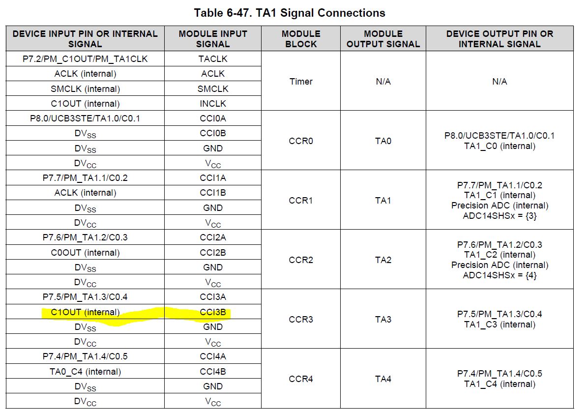
I think I can use COMP_E in MSP432, I find an COMP_E introduction saying "Output provided to Timer_A capture input", how can I use CIMP_E to trigger Timer_A?Is Timer_A capture mode using the COMP_E in MSP432? If so, how can I set Timer_A capture level?
If you refer to the TimerA Signal Connnection tables on page 128, , you can see that the comparator output and timer input share the connection. This is how the output is provided to the capture input (it can also be configured to the timer input).
The comparator and the timer are configured separately. The comparator will define the voltage level at which the digital capture signal is sent to the timer.
Please refer to the TRM to get a better undertanding of the timer configuration.
Also, there are examples for using the comparator and timer here:
Please note that there are several timers to choose from.
Regards,
Chris
I run this example
/* * ------------------------------------------- * MSP432 DriverLib - v3_21_00_05 * ------------------------------------------- * * --COPYRIGHT--,BSD,BSD * Copyright (c) 2016, Texas Instruments Incorporated * All rights reserved. * * Redistribution and use in source and binary forms, with or without * modification, are permitted provided that the following conditions * are met: * * * Redistributions of source code must retain the above copyright * notice, this list of conditions and the following disclaimer. * * * Redistributions in binary form must reproduce the above copyright * notice, this list of conditions and the following disclaimer in the * documentation and/or other materials provided with the distribution. * * * Neither the name of Texas Instruments Incorporated nor the names of * its contributors may be used to endorse or promote products derived * from this software without specific prior written permission. * * THIS SOFTWARE IS PROVIDED BY THE COPYRIGHT HOLDERS AND CONTRIBUTORS "AS IS" * AND ANY EXPRESS OR IMPLIED WARRANTIES, INCLUDING, BUT NOT LIMITED TO, * THE IMPLIED WARRANTIES OF MERCHANTABILITY AND FITNESS FOR A PARTICULAR * PURPOSE ARE DISCLAIMED. IN NO EVENT SHALL THE COPYRIGHT OWNER OR * CONTRIBUTORS BE LIABLE FOR ANY DIRECT, INDIRECT, INCIDENTAL, SPECIAL, * EXEMPLARY, OR CONSEQUENTIAL DAMAGES (INCLUDING, BUT NOT LIMITED TO, * PROCUREMENT OF SUBSTITUTE GOODS OR SERVICES; LOSS OF USE, DATA, OR PROFITS; * OR BUSINESS INTERRUPTION) HOWEVER CAUSED AND ON ANY THEORY OF LIABILITY, * WHETHER IN CONTRACT, STRICT LIABILITY, OR TORT (INCLUDING NEGLIGENCE OR * OTHERWISE) ARISING IN ANY WAY OUT OF THE USE OF THIS SOFTWARE, * EVEN IF ADVISED OF THE POSSIBILITY OF SUCH DAMAGE. * --/COPYRIGHT--*/ /******************************************************************************* * MSP432 Timer_A - VLO Period Capture * * Description: Capture a number of periods of the VLO clock and store them in * an array. When the set number of periods is captured the program is trapped * and the LED on P1.0 is toggled. At this point halt the program execution read * out the values using the debugger. * ACLK = VLOCLK = 14kHz (typ.), MCLK = SMCLK = default DCO = 3MHz * * MSP432P401 * ------------------ * /|\| | * | | | * --|RST P1.0 |---> P1.0 LED * | P2.4 |--- TA0.1 * | | | * | P4.2 |--- ACLK * | | * Author: Timothy Logan *******************************************************************************/ /* DriverLib Includes */ #include "driverlib.h" /* Standard Includes */ #include <stdint.h> #define NUMBER_TIMER_CAPTURES 20 /* Timer_A Continuous Mode Configuration Parameter */ const Timer_A_ContinuousModeConfig continuousModeConfig = { TIMER_A_CLOCKSOURCE_SMCLK, // SMCLK Clock Source TIMER_A_CLOCKSOURCE_DIVIDER_1, // SMCLK/1 = 3MHz TIMER_A_TAIE_INTERRUPT_DISABLE, // Disable Timer ISR TIMER_A_SKIP_CLEAR // Skup Clear Counter }; /* Timer_A Capture Mode Configuration Parameter */ const Timer_A_CaptureModeConfig captureModeConfig = { TIMER_A_CAPTURECOMPARE_REGISTER_1, // CC Register 2 TIMER_A_CAPTUREMODE_RISING_EDGE, // Rising Edge TIMER_A_CAPTURE_INPUTSELECT_CCIxB, // CCIxB Input Select TIMER_A_CAPTURE_SYNCHRONOUS, // Synchronized Capture TIMER_A_CAPTURECOMPARE_INTERRUPT_ENABLE, // Enable interrupt TIMER_A_OUTPUTMODE_OUTBITVALUE // Output bit value }; /* Statics */ static volatile uint_fast16_t timerAcaptureValues[NUMBER_TIMER_CAPTURES]; static volatile uint32_t timerAcapturePointer = 0; int main(void) { /* Stop watchdog timer */ MAP_WDT_A_holdTimer(); /* Configuring P1.0 as output */ MAP_GPIO_setAsOutputPin(GPIO_PORT_P1, GPIO_PIN0); /* Configuring P2.4 as peripheral input for capture and P4.2 for ACLK * output */ MAP_GPIO_setAsPeripheralModuleFunctionOutputPin(GPIO_PORT_P4, GPIO_PIN2, GPIO_PRIMARY_MODULE_FUNCTION); MAP_GPIO_setAsPeripheralModuleFunctionInputPin(GPIO_PORT_P2, GPIO_PIN4, GPIO_PRIMARY_MODULE_FUNCTION); /* Setting ACLK = VLO = 14kHz */ MAP_CS_initClockSignal(CS_ACLK, CS_VLOCLK_SELECT, CS_CLOCK_DIVIDER_1); /* Configuring Capture Mode */ MAP_Timer_A_initCapture(TIMER_A0_BASE, &captureModeConfig); /* Configuring Continuous Mode */ MAP_Timer_A_configureContinuousMode(TIMER_A0_BASE, &continuousModeConfig); /* Enabling interrupts and going to sleep */ MAP_Interrupt_enableSleepOnIsrExit(); MAP_Interrupt_enableInterrupt(INT_TA0_N); MAP_Interrupt_enableMaster(); /* Starting the Timer_A0 in continuous mode */ MAP_Timer_A_startCounter(TIMER_A0_BASE, TIMER_A_CONTINUOUS_MODE); MAP_PCM_gotoLPM0(); } //****************************************************************************** // //This is the TIMERA interrupt vector service routine. // //****************************************************************************** void TA0_N_IRQHandler(void) { uint32_t jj; MAP_Timer_A_clearCaptureCompareInterrupt(TIMER_A0_BASE, TIMER_A_CAPTURECOMPARE_REGISTER_1); timerAcaptureValues[timerAcapturePointer++] = MAP_Timer_A_getCaptureCompareCount(TIMER_A0_BASE, TIMER_A_CAPTURECOMPARE_REGISTER_1); if (timerAcapturePointer >= NUMBER_TIMER_CAPTURES) { while (1) { MAP_GPIO_toggleOutputOnPin(GPIO_PORT_P1, GPIO_PIN0); for(jj=0;jj<10000;jj++); } } }
The comments say ACLK = 14KHz, P4.2 output. I connect P4.2 and P2.4, when LED(P1.0) toggle, I stop to read the timerAcaptureValues array.
I can see a series of "313 626 939 1253 1566...", indecading Timer_A counting 313 number per rising edge.
See that the Timer_A count at a rate of 3MHz:
/* Timer_A Continuous Mode Configuration Parameter */ const Timer_A_ContinuousModeConfig continuousModeConfig = { TIMER_A_CLOCKSOURCE_SMCLK, // SMCLK Clock Source TIMER_A_CLOCKSOURCE_DIVIDER_1, // SMCLK/1 = 3MHz TIMER_A_TAIE_INTERRUPT_DISABLE, // Disable Timer ISR TIMER_A_SKIP_CLEAR // Skup Clear Counter };
So 313 number represents 3000000/313 = 9584.6645Hz, not the ACLK 14KHz.Why?
**Attention** This is a public forum