This thread has been locked.

If you have a related question, please click the "Ask a related question" button in the top right corner. The newly created question will be automatically linked to this question.

MSP430I2041: MPPT on msp430i

Part Number: MSP430I2041
Other Parts Discussed in Thread: EVM430-I2040S,

Hello TI

I want to build with your help MPPT on msp430i components.

Is finished version 2 of my MPPT. This MPPT is more better then comercial.

1. Can provide load directly from SOLAR cells (4Panels*37-45V=140V)  to any heating elements or someone else, do not use via inverter.

2. Low cost.

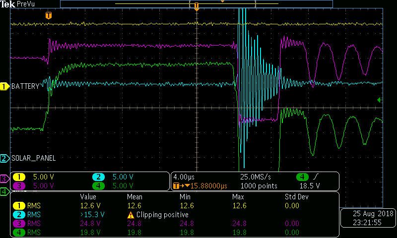
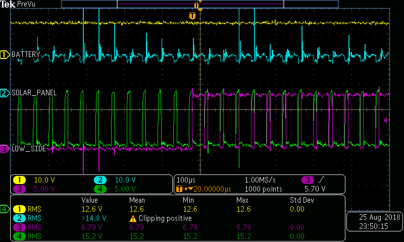
Now is work fine but today I observe my MSP starting overheating if only I connect VCC(3.3V) , GnD , RST and Test. If stay supplied to much time can put hand on  MSP430 is too hot and also can't flashing. I put oscilloscope to look on pins and see only consumption on pin VCC (100mA), power down to 3.0V.

Do you have specialist in hardware to help me to review my schematic?

Maybe propose to change drivers to another, I don't now. I wait any observation.

I think tomorrow I plane to replace MSP430 to another.

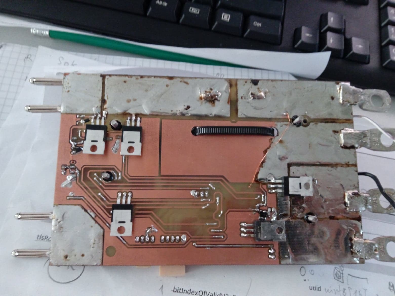
Tomorrow I will public my final PCB :) .

 MPPT schematic.pdf

  • R17 R32 R33 R34 changin to 10Ohm -- is only for filtering some spikes when you connect the battery.
    How do you think : in case if VCC (3v3) increase slower to 3.3V when ADC pins or to Digital Pin, is bad ?
  • Is also broke 2 IR2106, whi I dont now , side ho command Q2 and Q3.
    I put Zener for 15V do not prevent more 20V offset.
    I will try remove D4(zener on 15 V to protect base of mossfet) and remove D3 and D1 tomorrow.
  • Is starting heating after few hours of debugging and calibration on read ADCs (voltage read, Amps read )
  • Hello Serghei,

    Hot can be relative, but your MSP430 should not get very hot during operation. If you're measuring 100mA going into the device, then I suspect something is wrong or damaged. According to the datasheet, active mode at 16.384MHz is less than 5mA. Looking at your schematic, I see that you're not following the guidelines in our datasheet. For example, ROSC is open, you're using 100nF capacitor on VCORE, etc. Please refer to the target board schematic for the MSP430i2041 and the schematic for the EVM430-i2040S as references.
  • Hello James Evans, and thanks for observation

    About your observation I made:

    1. ROSC put AVSS according datasheet.

    2. Pull Up on RST pin change from 4K7 to 47K

    3. Change C on RST pin from 1nF to 2.2nF

    4. To protect SD24 pins add for each resistors and Capacitors like  EVM430-i2040S page 59.

    5. change Capacitor Ratio between Vcore and VCC. in case if CVcore is 470nF the Cof VCC need to be minimumm 4.7uF (1:10).

    After this changes I try to leave the comment.

  • I broke last my 2 MSP samples :) BUT in finally I finished to do protection on the last MSP :): short circuit big spikes ...

    can look in the picture:  

    Start the DC-DC converter in asynchronous mode and when consumtion is more 500mA(configurable by software) start in Synchronous mode; like picture


    My MPPT look like this:

  • Hello Serghei,

    Thanks for sharing these images with our community. Have you resolved your issue?

    Regards,

    James
  • Hello James
    I replace with new uC from TI(sample) and now its work without any modification. Precedence uC work but only on the begin when is cold(can flash, can debug, serial work) but after few seconds is stop working and is very hot(can't debugging , flashing and not work serial). I every time disconnect power supply when stop working and is very hot. I don't have any idea why is heating. I leave for later investigation.
  • Hello Serghei,

    do you assume an ideal I/V solar cell stack characteristic or do you deal with Global MPPT?
  • I Build Custom I/V. But the best option on this MPPT is can to provide Voltage from solar panel directly to any load (heat element) !!! and not via inverter.(DC-AC inverter). Can be capably to notify via SMS or CALL if someone want to steal your panel solar. Low cost!! < 100$ 200V 50A. Can be change to any another voltage. Ex. 4 series VP 45V *4 = 180V open circuit. I give resistence to heat water and in case if I have power and the battery is full can stock energy to hot water to cold the hows (Air Condition) ...

    DC AC have 2 steeps:

    1. Boost the voltage from 12/24/48V to 300-400V.

    2. From Boosted power create AC voltage for 220V.

    And this MPPT is capable in case if you have in series more VP (450V, 10VP*45V open circuit=450V) to provide current dirrecty to Boosted power, now Inverter need only to create sinus Voltage.

    I created all what I say on msp430i2041 :). Is little bit difficult to use uC on 16Mhz. 2 timers only :) and also provide sinhronization via UART and + SPI for display and ++++++ alghoritm.

    I finished my 3rd part of board with compactors and few and gates to protect any bad soft algorithm.

    If any guy want to help me and want to create with me MPPT I am glad. 

  • My question was about algorithm and how do you deal with a case when solar cells have a different irradiance.
    It can be caused by water, dust, shade, birds, etc.

  • The alghorithm based on trigger every conversion time of ADC and try to fiend MPPT. Algorithm used "Incremental conductance ".


  • O.K.
    my picture on the right shows 3 power maximums.
    No guarantee that your algorithm would find the best maximum, this one on the right.
    In case of a big disturbance it could go the top in the middle and stay there until a shade or dirt is removed.
  • Ok, Now I understand your observation. Can you provide me any hint about your algorithm? Where I can fiend documentation or flow for your algorithm?

    Thanks. 

  • Try to start from highest possible voltages, close to zero current and then use your algorithm.
    How often such a scan?
    1 time per minute?
    Depends on an environment.

**Attention** This is a public forum