This thread has been locked.

If you have a related question, please click the "Ask a related question" button in the top right corner. The newly created question will be automatically linked to this question.

MSP430F5529: Clock Speed: DCOCLK vs. DCOCLKDIV

Part Number: MSP430F5529
Other Parts Discussed in Thread: MSP-EXP430F5529LP

I am trying to understand the difference between using DCOCLK vs. DCOCLKDIV in the SELM field of UCSCTL4. From what I have read in the Users Guide and other resources, I expect the following:

Using DCOCLK,         fDCOCLK = D x (N + 1) x (fFLLREFCLK / n)

Using DCOCLKDIV,   fDCOCLKDIV = fDCOCLK / D,  or   fDCOCLKDIV = (N + 1) x (fFLLREFCLK / n)

where

D is the divider from the FLLD field of UCSCTL2,

N is the multiplier from the FLLN field of UCSCTL2

fFLLREFCLK is the frequency of the reference clock selected by the SELREF field of UCSCTL3

n is the divider from the FLLREFDIV field of UCSCTL3

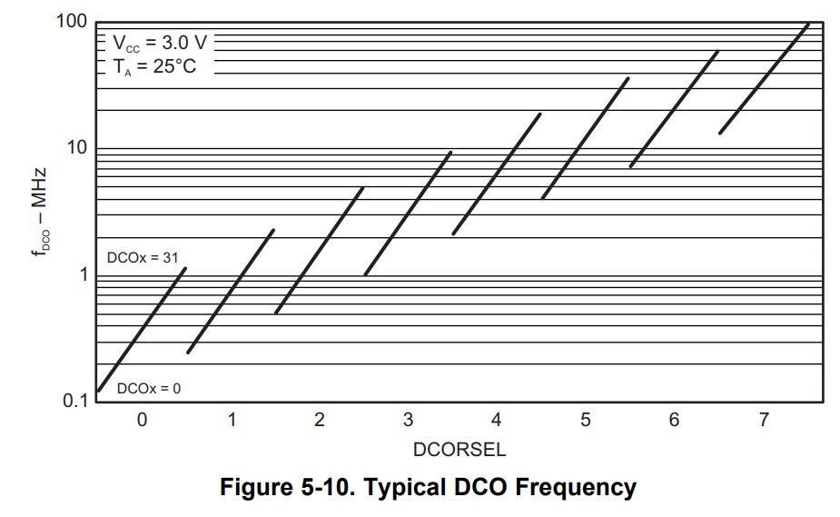
and the appropriate DCORSEL value in UCSCTL1 is chosen for the frequency range.

The problem is I see the same behavior whether I use DCOCLK or DCOCLKDIV: the LED toggles once per second either way.

UCSCTL4 |= SELA__REFOCLK + SELM__DCOCLK;
UCSCTL4 |= SELA__REFOCLK + SELM__DCOCLKDIV;

Can anyone see what I am missing?

Thanks!

Mike

Here's the code, derived from the TI demo examples:

#include <msp430.h>

int main(void)
{
	WDTCTL = WDTPW+WDTHOLD;                                     // Stop WDT

	P1DIR |= BIT0;                                                                  // P1.0 output to red LED

	UCSCTL3 = SELREF__REFOCLK;                                  // Set DCO FLL reference = REFO
	UCSCTL4 |= SELA__REFOCLK + SELM__DCOCLK;     // Set ACLK = REFO, Select DCOCLK
	UCSCTL0 = 0x0000;                                                         // Set lowest possible DCOx, MODx

	__bis_SR_register(SCG0);                                                // Disable the FLL control loop
	UCSCTL1 = DCORSEL_5;                                                // Select DCO range 16MHz operation
	UCSCTL2 |= 249;                  		                                   // Set DCO Multiplier for 8MHz
	                                                                                                           // (N + 1) * FLLRef = Fdco
	                                                                                                           // (249 + 1) * 32768 = 8MHz
	__bic_SR_register(SCG0);                                                // Enable the FLL control loop


	while(1)
	{
		P1OUT ^= BIT0;
		__delay_cycles(8000000);                                         // Delay: toggle once/s
	}
}

  • Hello Mike,

    I suspect it's related to the UCS11 errata, which is triggered by modifying UCSCTL4. Halting your code at the delay line inside the while(1) loop, I noticed that all XT2, XT1, and DCO fault flags are set. Thus, these fault flags could be causing things to operate the same even though you're configurations are different. Also, under the Special Function Registers, I see that OFIFG (oscillator fault flag) is set.

    Regards,

    James
  • James,

    Thanks. I did neglect the sample code that appears to handle fault flags...looks like I will need to dig in. I'll check it out and report back.

    Mike
  • Still having trouble. I read the UCS11 errata and understand that the fault flags can be set inadvertently when changing UCSCTL4, and the work-around is to clear the flags after changing UCSCTL4. I added the following code to do that (it is from the TI example program)

    // Loop until XT1,XT2 & DCO stabilizes - In this case only DCO has to stabilize
    do
    {
    UCSCTL7 &= ~(XT2OFFG + XT1LFOFFG + DCOFFG);
    // Clear XT2,XT1,DCO fault flags
    SFRIFG1 &= ~OFIFG; // Clear fault flags
    }while (SFRIFG1 & OFIFG); // Test oscillator fault flag


    The code gets trapped in the do-while loop because the XT1LFOFFG and OFIFG bits never remain cleared. I also tried putting the do-while code at the top of the main() function before doing anything else, and the flags remain set, which means that the fault is a result of something other than changing UCSCTL4 (or any other register).

    I tried testing the DCOFFG bit to exit the do-while loop, and it does exit to execute the rest of the code, but the original behavior persists (and the faults persist as well).

    I am not sure what to do next. I am using the MSP-EXP430F5529LP LaunchPad and programming it with CCS Version: 8.1.0.00011 if that offers any clues...

    Thanks.

    Mike
  • I seem to have it working now. One brain cramp that I overcame was to actually select the crystal inputs for XT1 and XT2. The next was to wait for the three clocks to stabilize individually, and in this order: XT1CLK, XT2CLK, and (once the FLL finished dialing it in) DCOCLK. Here is the code:

    /*
     * Set up UCS MCLK for 4 MHz
     * 		Use XT1 (default) for reference FLLRef = 32768 Hz
     * 		Use DCOCLK for MCLK
     * 				D * (N + 1) * FLLRef = Fdco
     * 				D = 1/2
     * 				N = 243
     * 				FLLRef = 32768
     */
    
    #include <msp430.h>
    
    int main(void)
    {
    	WDTCTL = WDTPW+WDTHOLD;				// Stop WDT
    
    	P1DIR |= BIT0;						// P1.1 output to red LED
    	P5SEL |= BIT4 + BIT5;				// select 32768-Hz crystal on P5.4 and pP.5
    	P5SEL |= BIT2 + BIT3;				// select 4-MHz crystal on P5.2 and pP.3
    
    	//UCSCTL3 = SELREF__REFOCLK;			// Set DCO FLL reference = REFO (default XT1CLK, but sets fault flag)
    	UCSCTL4 |= SELM__DCOCLK;			// Set MCLK = DCOCLK (ACLK default XT1CLK; SELS and SELM default DCOCLKDIV)
    
    	// Loop until XT1 stabilizes
    	do
    	{
    		UCSCTL7 &= ~XT1LFOFFG;
    	}while (UCSCTL7 & XT1LFOFFG);		// Test oscillator fault flag
    
    	// Loop until XT2 stabilizes
    	do
    	{
    		UCSCTL7 &= ~XT2OFFG;
    	}while (UCSCTL7 & XT2OFFG);			// Test oscillator fault flag
    
    	// set DCO fields and let the FLL work its magic
    	__bis_SR_register(SCG0);			// Disable the FLL control loop
    	UCSCTL0 = 0x0000;					// Set lowest possible DCOx, MODx
    	UCSCTL1 = DCORSEL_4;				// Select DCO range 8MHz operation
    	UCSCTL2 |= FLLD__2 + 243;			// Set DCO Multiplier for 8MHz
    	                                           //  D  * ( N  + 1) * FLLRef = Fdco
    	                                           // 1/2 * (243 + 1) * 32768  = 4.000MHz
    	__bic_SR_register(SCG0);			// Enable the FLL control loop
    
    	// Loop until DCO stabilizes
    	do
    	{
    		UCSCTL7 &= ~DCOFFG;
    	}while (UCSCTL7 & DCOFFG);			// Test oscillator fault flag
    
    	// Clear overall oscillator fault flag
    	SFRIFG1 &= ~OFIFG;					// Clear OFIFG fault flag
    
    	//*************************************************************
    	// Blink the LED to check the clock rate
    	while(1)
    	{
    		P1OUT ^= BIT0;
    		__delay_cycles(4000000);		// Delay for 1 second at 4 MHz
    	}
    }
    

    There is probably a better way, and I would welcome any advice.

    One question I still have is about selecting the DCORSEL value; is it selected based on the final frequency for the DCOCLK or DCOCLKDIV when using the FLLD divider? In other words, for 8 MHz, for instance, DCORSEL_5 appears to be a good choice, but if I am using FLLD__8 to get the DCOCLK to 1 MHz, which is down from the DCOCLKDIV at 8 MHZ, then would DCORSEL_2 be more appropriate?

    Thanks.

    Mike

  • Hi Mike,

    Nice work! I'll spend some time tomorrow digging into this to find an explanation.

    Regards,

    James
  • Hi again Mike,

    Michael Prairie said:
    One question I still have is about selecting the DCORSEL value; is it selected based on the final frequency for the DCOCLK or DCOCLKDIV when using the FLLD divider? In other words, for 8 MHz, for instance, DCORSEL_5 appears to be a good choice, but if I am using FLLD__8 to get the DCOCLK to 1 MHz, which is down from the DCOCLKDIV at 8 MHZ, then would DCORSEL_2 be more appropriate?

    For a DCO frequency of 8MHz, setting DCORSEL equal to 2 isn't recommended because the frequency range only covers from approximately 0.5 MHz up to 5 MHz. Setting DCORSEL equal to 5 is much better for 8 MHz since the frequency range covers from 4 MHz to almost 40MHz. You can read more about these recommendations by referring to Section 5.19 (specifically Footnote #1) and Figure 5-10 in the datasheet.

    I hope this helps clear things up.

    Regards,

    James

  • Hi James,

    I did use the datasheet to determine what DCORSEL to use. My question was whether the choice applied to DCOCLK or DCOCLKDIV. Now I see that it applies to DCOCLK.

    Thanks so much for your help.

    Mike

**Attention** This is a public forum