This thread has been locked.

If you have a related question, please click the "Ask a related question" button in the top right corner. The newly created question will be automatically linked to this question.

MSP430G2553: Help with interfacing with HX711 chip for weight sensor

Part Number: MSP430G2553

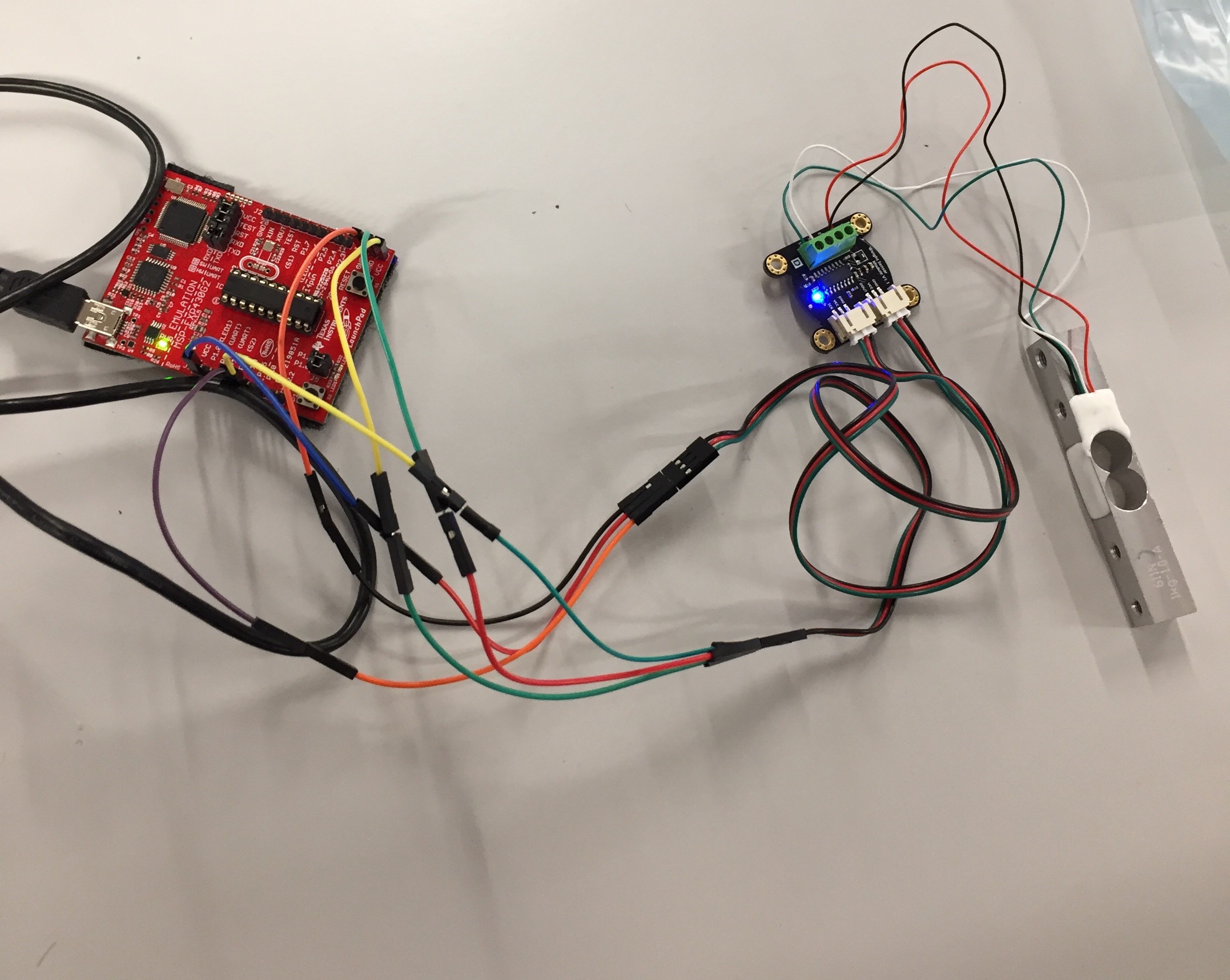
Hello everyone, I’m currently having an issue getting the SEN0160 weight sensor to work with the MSP430g2553. The SEN0160 uses the HX711 ADC chip (all datasheets attached below). I am not able to read the data coming from the chip and it’s definitely a hardware issue because I measured the voltage at the load cell connections and I’m getting a measured voltage of 2.5 at the E+ port. According to the datasheet the range is 2.6-5.5 V. The load cell itself I think needs 5 volts excitation, but I’m not even reaching the minimum 2.6 volts when I’m powering the hx711 ADC with 5 volts through a 5 Volts DC power supply. I posted some pictures below to help clarify. I actually connected the DOUT and SCK pins to P2.3 and P2.4 not the uart pins as shown below. 


https://www.dfrobot.com/wiki/index.php/Weight_Sensor_Module_SKU:SEN0160


www.mouser.com/.../hx711_english-1022875.pdf

  • What does "not able to read the data" mean? All-0s or all-1s on DOUT? Random data on DOUT? MCU resets?

    Don't power the SEN0160 from 5V since that's presumably the level that will come out on DOUT, which could damage the MCU. The data sheet seems to think 3.3V (really 3.6V) power from the Launchpad should be fine. [Edit: HX711 Data Sheet p. 4:  "Digital power supply (DVDD) should be the same power supply as the MCU power supply."]

  • Sorry I should clarify, I get random data from DOUT. Basically no change in data if I put pressure on the weight sensor, just fluctuating values However doesn't the load cell (bridge sensor) need 5 volts itself? From the datasheet it says the load cell needs excitation voltage 5-15 V. How would I do this if I'm powering the Hx711 ADC with the msp430? I measured E+ and I still get only 2.5 V on the E+ line to the load cell.

  • The HX711 is generating the excitation (E+), and you can't provide the HX711 with 15V, so I they may be trying to say something else there.

    E+ = AVDD (from the internal regulator), and data sheet p.4 says "Vavdd=Vbg*(R1+R2)/ R1" where (p.3) Vbg=1.25V and (SEN0160 schematic) R1=R2=10K. My calculator says that's 1.25V*(10K+10K)/10K=2.5V, so that sounds right. If I remember my bridges, S+ and S- should each read around half this, 1.25V.

    The serial protocol looks rather arcane. Are you pretty sure you've got that right?

    [Edit: On re-reading it looks like the "Weight Sensor" is the bar with the strain gauges, so maybe they provide that spec in case you want to use it separately. As I read it, their board will always provide E+=2.5V, which seems like a mis-match. On the other hand, strain gauges really aren't that picky about voltage.]

  • Oh I see that makes a whole lot of sense. I'm actually not sure how to set up the connections from the ADC to the MSP430. I assumed that the black ground lines coming from the ADC board are to be grounded with the MCU's ground. And then the VCC lines to the VCC of the MSP430, which I measured with a multimeter to be around 3.5 volts. And the DOUT and SCK connections to the respective I/O pins, which I chose to use P2.3 and P2.4. But then when I measure the load cell connections, E+, E-, S-, and S+ I get the expected 2.5 volts for E+, close to zero for E- since that is ground and is expected, but I also get like around 6 to 8 mV for S- and S+. Maybe that is the problem? It should be half the VCC line, so 1.25 volts?
  • [I'm working from memory here. If someone tells you something different, believe that.]

    Each side of the bridge constitutes a simple voltage divider. In a balanced bridge (all the R-s are the same) each is a divide by 2. Differencing the two S levels gives you something near 0.

    In theory, you could just use one of the dividers, but the bridge gives you temperature compensation. (Strain gauges are finicky creatures.) Passing a non-zero voltage over the S wires helps with noise.

    So yes: I would expect S+/S- to (each) be around 2.5V/2=1.25V w.r.t. GND, and around 0 w.r.t. each other. I'm not sure how the HX711 would even influence this (short of driving INNA/INPA, which sounds pathological).

    [Edit: What resistance do you see across each of the resistors? (E+->S+, E+->S-, S-->E-, S+->E-) They should all be about the same; my guess is about 350 ohms, since 350-ohm gauges are very common.]

**Attention** This is a public forum