This thread has been locked.
If you have a related question, please click the "Ask a related question" button in the top right corner. The newly created question will be automatically linked to this question.
Tool/software: Code Composer Studio
Hi,
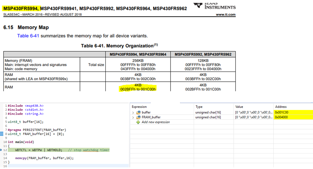
I'm trying to determine how much power is consumed when copying two data buffers (~3KB in total) to/from SRAM <-> FRAM. I'm using memcpy to copy data between SRAM and FRAM, not using DMA.
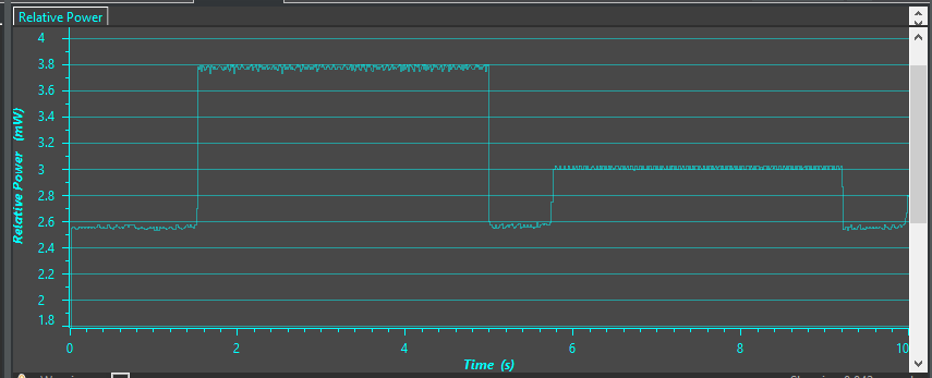
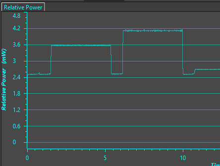
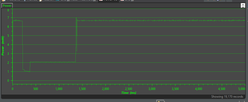
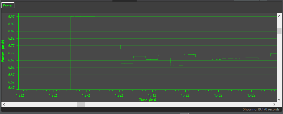
I'm trying to use EnergyTrace (CCSv8) for this purpose. I have set markers in the code (e.g. toggling GPIO / output to UART etc.) but these markers are not seen in the Energy Trace power output (attached).
The initial spike seen is I think the clocks being setup ?, but where's the gpio toggling power consumption ?
The whole FRAM<->SRAM data transfer takes about 3ms each, so i've zoomed in the plot.
CPU is running in Active power mode. Energy trace is used in standalone mode.
Is there a better way to determine the power consumption for a FRAM read/write ?
Thank you
I have some code like the following:
/* * main.c * */ #include "conf.h" #include "utils/myuart.h" /******************************************************* * Globals *******************************************************/ unsigned char Buff_First[16*96]; unsigned char Buff_Second[16*96]; uint8_t *Buff_First_ptr = (uint8_t *)&Buff_First; uint8_t *Buff_Second_ptr = (uint8_t *)&Buff_Second; /******************************************************* * FUNC DEFS *******************************************************/ void benchmark_buff_checkpoint_latency(void); /************************************************************************************* * MAIN *************************************************************************************/ void main(void) { /* mandatory init stuff */ WDTCTL = WDTPW | WDTHOLD; //Stop WDT PM5CTL0 &= ~LOCKLPM5; // Disable the GPIO power-on default high-impedance mode to activate previously configured port settings system_init(); // init clocks, UART setupDebugPins(); // setup pins as output GPIO pins benchmark_buff_checkpoint_latency(); while(1){ __no_operation(); } } /************************************************************************************* * BENCHMARKING *************************************************************************************/ void benchmark_buff_checkpoint_latency(void){ _DBGUART("aaaaaaaaaaaaaaaaaaaaaaaaaaaaaaaaaaaaaaaaaa %d \r\n", 123); _DBGUART("aaaaaaaaaaaaaaaaaaaaaaaaaaaaaaaaaaaaaaaaaa %d \r\n", 123); GPIO_toggleOutputOnPin( GPIO_PORT_P1, GPIO_PIN1 ); GPIO_toggleOutputOnPin( GPIO_PORT_P1, GPIO_PIN1 ); GPIO_toggleOutputOnPin( GPIO_PORT_P1, GPIO_PIN1 ); /* from SRAM to FRAM */ Buffer_backup(Buff_First_ptr, Buff_Second_ptr); _DBGUART("aaaaaaaaaaaaaaaaaaaaaaaaaaaaaaaaaaaaaaaaaa %d \r\n", 123); _DBGUART("aaaaaaaaaaaaaaaaaaaaaaaaaaaaaaaaaaaaaaaaaa %d \r\n", 123); GPIO_toggleOutputOnPin( GPIO_PORT_P1, GPIO_PIN1 ); GPIO_toggleOutputOnPin( GPIO_PORT_P1, GPIO_PIN1 ); GPIO_toggleOutputOnPin( GPIO_PORT_P1, GPIO_PIN1 ); /* from FRAM to SRAM */ Buffer_restore(Buff_First_ptr, Buff_Second_ptr); _DBGUART("aaaaaaaaaaaaaaaaaaaaaaaaaaaaaaaaaaaaaaaaaa %d \r\n", 123); _DBGUART("aaaaaaaaaaaaaaaaaaaaaaaaaaaaaaaaaaaaaaaaaa %d \r\n", 123); GPIO_toggleOutputOnPin( GPIO_PORT_P1, GPIO_PIN1 ); GPIO_toggleOutputOnPin( GPIO_PORT_P1, GPIO_PIN1 ); GPIO_toggleOutputOnPin( GPIO_PORT_P1, GPIO_PIN1 ); }
I guess the issue might be related with granularity ?
I proceeded with the following:
I ran the memcpy (SRAM <-> FRAM) iteratively for 1000 times as below:
for (i=0;i<1000;i++){ Buff_backup(Buff_First_ptr, Buff_Second_ptr); // copy both buff1 and buff2 to FRAM from SRAM using memcpy }
same as above for reading back from FRAM to SRAM.
And I got the below.
According to this, FRAM write consumes much more power than FRAM reads.
FRAM write = ~1mW,
FRAM read = ~0.2mW
Am I reading this measurement correctly ?
Is there a way to find out the energy consumed during only the read/write periods ?
thanks
Hi Dennis,
Correct - the two buffers are in SRAM, then inside Buff_backup(Buff_First_ptr, Buff_Second_ptr);
, memcpy is used to copy both first and second buffer to two buffers in FRAM. like so:
void Buff_backup(uint8_t *buff1_ptr, uint8_t *buff2_ptr){ memcpy(Buff_First_FRAMStorage_ptr, buff1_ptr, 16*96); memcpy(Buff_Second_FRAMStorage_ptr, buff2_ptr, 16*96); }
eg. of how the buffer is in FRAM (compiler/linker decides on the fram location):
#pragma PERSISTENT(Buff_First_FRAMStorage)
unsigned char Buff_First_FRAMStorage[16*96] = {0};
and then i do the reverse memcpy, to copy from FRAM back to SRAM.
it's worth mentioning i'm using clock SMCLK=MCLK=8MHz.
so two questions:
1) why is my FRAM read energy/power different to the FRAM write ?
2) at 8MHz, does SRAM and FRAM have the same r/w latency & energy ? if yes, why do we need to use SRAM at lower clock speeds ?
thanks
Hi Rosh,
Ok. Let's try this...in CCS on the menu on the top you can select View>Expressions to open an expressions window.
In the expression window, add your variable names and tell me what address they are located at.
I did something similar. See below. Notice that my variable 'buffer' is assigned to RAM. My other variable 'FRAM_buffer' is assigned to FRAM, but I had to use the #pragma PERSISTENT in order for the linker to place it there.
Also, take a look at the MSP430 FRAM Technology - How To and Best Practices.
Hi Dennis,
that is what I did as well. see code and screenshot attached, to confirm what you have said.
/* * main.c * * Created on: Nov 27, 2018 * Author: Rosh * * Notes: * - FRAM read/write speed/energy testing */ #include "conf_EPD.h" #include <stdint.h> #include <string.h> #include <stdlib.h> #include <stdio.h> #include "driverlib.h" // general utilities #include "utils/myuart.h" //#include "utils/stopwatch.h" /******************************************************* * Globals *******************************************************/ #define CLK_SPEED_8MHz 1 #define CLK_SPEED_16MHz 0 #define BUFF_SIZE 16*96 // buffers in SRAM unsigned char SRAM_Buff1[BUFF_SIZE]; unsigned char SRAM_Buff2[BUFF_SIZE]; // buffers in FRAM #pragma PERSISTENT(FRAM_Buff1) unsigned char FRAM_Buff1[BUFF_SIZE] = {0}; #pragma PERSISTENT(FRAM_Buff2) unsigned char FRAM_Buff2[BUFF_SIZE] = {0}; //unsigned int FreqLevel = 7; //int uartsetup=0; /******************************************************* * FUNC DEFS *******************************************************/ // benchmarks void benchmark_exp0(void); void _buffer_populate(uint8_t *Buff_ptr, uint8_t data_byte); // setup related //void uart_setup(void); //void clock_setup(void); // helpers void _delay(uint32_t d); // debug void setupDebugPins(void); /************************************************************************************* * SETUP *************************************************************************************/ /* void uart_setup(void){ uartsetup=0; uartinit(); } void clock_setup(void){ #if CLK_SPEED_8MHz //Set DCO Frequency to 8MHz CS_setDCOFreq(CS_DCORSEL_0, CS_DCOFSEL_6); //configure MCLK, SMCLK to be source by DCOCLK CS_initClockSignal(CS_MCLK, CS_DCOCLK_SELECT, CS_CLOCK_DIVIDER_1); //16mhz CS_initClockSignal(CS_SMCLK, CS_DCOCLK_SELECT, CS_CLOCK_DIVIDER_1); // 16mhz #endif #if CLK_SPEED_16MHz #endif __bis_SR_register(GIE); //Verify if the Clock settings are as expected volatile uint32_t clockValue; clockValue = CS_getMCLK(); clockValue = CS_getACLK(); clockValue = CS_getSMCLK(); if(clockValue); } */ /************************************************************************************* * buffer related *************************************************************************************/ void _buffer_populate(uint8_t *Buff_ptr, uint8_t data_byte){ uint32_t i; for(i=0; i < BUFF_SIZE; i++){ Buff_ptr[i] = data_byte; } } /************************************************************************************* * DEBUG *************************************************************************************/ void setupDebugPins(void){ /* launchpad LEDs */ GPIO_setAsOutputPin( GPIO_PORT_P1, GPIO_PIN0 ); GPIO_setAsOutputPin( GPIO_PORT_P1, GPIO_PIN1 ); GPIO_setOutputLowOnPin( GPIO_PORT_P1, GPIO_PIN0 ); GPIO_setOutputLowOnPin( GPIO_PORT_P1, GPIO_PIN1 ); } /************************************************************************************* * MAIN *************************************************************************************/ void main(void) { /* mandatory init stuff */ WDTCTL = WDTPW | WDTHOLD; //Stop WDT PM5CTL0 &= ~LOCKLPM5; // Disable the GPIO power-on default high-impedance mode to activate previously configured port settings uint16_t i; clock_setup(); uart_setup(); setupDebugPins(); _DBGUART("\r\n -- FINISHED SYS/BOARD SETUP 2-- \r\n"); _DBGUART("SMLK= %l ; MCLK= %l ; ACLK=%l \r\n", CS_getSMCLK(), CS_getMCLK(), CS_getACLK()); _delay(1000000); /* initialize the buffers in SRAM */ _buffer_populate(SRAM_Buff1, (uint8_t)0xFF); // buff init _buffer_populate(SRAM_Buff2, (uint8_t)0xFF); // buff init _delay(1000000); /* fram write */ for(i=0; i<1000; i++){ memcpy(FRAM_Buff1, SRAM_Buff1, BUFF_SIZE); memcpy(FRAM_Buff2, SRAM_Buff2, BUFF_SIZE); } _delay(1000000); /* fram read */ for(i=0; i<1000; i++){ memcpy(SRAM_Buff1, FRAM_Buff1, BUFF_SIZE); memcpy(SRAM_Buff2, FRAM_Buff2, BUFF_SIZE); } _delay(1000000); _DBGUART("\r\n -- DONE -- \r\n"); } /************************************************************************************* * BENCHMARKING *************************************************************************************/ /************************************************************************************* * HELPER FUNCTIONS *************************************************************************************/ void _delay(uint32_t d){ uint32_t i; for (i=0;i<d;i++){__no_operation();} } void UARTIntHandler() {}
code:
#define BUFF_SIZE 16*96 // buffers in SRAM unsigned char SRAM_Buff1[BUFF_SIZE]; unsigned char SRAM_Buff2[BUFF_SIZE]; // buffers in FRAM #pragma PERSISTENT(FRAM_Buff1) unsigned char FRAM_Buff1[BUFF_SIZE] = {0}; #pragma PERSISTENT(FRAM_Buff2) unsigned char FRAM_Buff2[BUFF_SIZE] = {0};
memory locations:
.bss 0 00001c00 00000c94 UNINITIALIZED
00001c00 00000600 (.common:SRAM_Buff1)
00002200 00000600 (.common:SRAM_Buff2)
.TI.persistent
* 0 00004000 00000c02
00004000 00000600 main_pdi_exp_rawbenchmarking.obj (.TI.persistent:FRAM_Buff1)
00004600 00000600 main_pdi_exp_rawbenchmarking.obj (.TI.persistent:FRAM_Buff2)
confirmed the above locations in watch expressions as well. locations are as above.
Strange though, on the *.map file the length = 600 for the buffers, but in the CCS memory allocation window and the watch expressions windows show that the length = 1536 (BUFF_SIZE). why is *.map reporting differently ?
anyway, sticking to the topic, when I run the attached code, i get this :
FRAM Read energy is lower than FRAM Write, but speeds are the same.
same buffer size. using 1000 runs of memcpy.
Why is this ?
When I remove memcpy and simply copy data in a loop :
/* fram write */ for(i=0; i<1000; i++){ for (j=0;j<BUFF_SIZE;j++){ FRAM_Buff1[j]=SRAM_Buff1[j]; } for (j=0;j<BUFF_SIZE;j++){ FRAM_Buff2[j]=SRAM_Buff2[j]; } } _delay(1000000); /* fram read */ for(i=0; i<1000; i++){ for (j=0;j<BUFF_SIZE;j++){ SRAM_Buff1[j]=FRAM_Buff1[j]; } for (j=0;j<BUFF_SIZE;j++){ SRAM_Buff2[j]=FRAM_Buff2[j]; } }
I get the opposite behavior (reads consume more power than writes).. very strange..
of course, in the above (and also in the memcpy case), every FRAM read incurs a SRAM write and vice versa. but it still doesn't explain the asymmetric power consumption behavior.
Any thoughts ?
Hi Dennis,
I looked at my disassembly, and something strange came up.
171 for(i=0; i<1000; i++){ 01041c: 430E CLR.W R14 01041e: 903E 03E8 CMP.W #0x03e8,R14 010422: 2C1A JHS (0x0458) 172 for (j=0;j<BUFF_SIZE;j++){ $C$L13: 010424: 430F CLR.W R15 010426: 903F 0600 CMP.W #0x0600,R15 01042a: 2C07 JHS (0x043a) 173 SRAM_Buff1[j]=FRAM_Buff1[j]; $C$L14: 01042c: 4FDF 4000 1C00 MOV.B 0x4000(R15),0x1c00(R15) 172 for (j=0;j<BUFF_SIZE;j++){ 010432: 531F INC.W R15 010434: 903F 0600 CMP.W #0x0600,R15 010438: 2BF9 JLO (0x042c) 175 for (j=0;j<BUFF_SIZE;j++){ $C$L15: 01043a: 430F CLR.W R15 01043c: 903F 0600 CMP.W #0x0600,R15 010440: 2C07 JHS (TA3_TA3R) 176 SRAM_Buff2[j]=FRAM_Buff2[j]; $C$L16: 010442: 4FDF 4600 2200 MOV.B 0x4600(R15),0x2200(R15) 175 for (j=0;j<BUFF_SIZE;j++){ 010448: 531F INC.W R15 01044a: 903F 0600 CMP.W #0x0600,R15 01044e: 2BF9 JLO (TA3_TA3CCTL0) 171 for(i=0; i<1000; i++){ $C$L17: 010450: 531E INC.W R14 010452: 903E 03E8 CMP.W #0x03e8,R14 010456: 2BE6 JLO (0x0424)
above section is for the below C code:
/* fram read */ for(i=0; i<100; i++){ for (j=0;j<BUFF_SIZE;j++){ SRAM_Buff1[j]=FRAM_Buff1[j]; } for (j=0;j<BUFF_SIZE;j++){ SRAM_Buff2[j]=FRAM_Buff2[j]; } }
What I'm confused is why are there references to Timers in the loop ?? (highlighted above in bold : e.g. TA3_TA3R, TA3_TA3CCTL0
it should be a straightforward, compare and jump if hi/low right ?
could this be the reason my FRAM read is acting strange ?
there is some other code in the project that is being built, but they are not being included or executed. (no *.h being included from the other project files), so it cant be external interference could it ?
below are my compiler settings :
-vmspx --data_model=restricted --use_hw_mpy=F5 --include_path="${CCS_BASE_ROOT}/msp430/include" --include_path="${workspace_loc:/${ProjName}/driverlib/MSP430FR5xx_6xx}" --include_path="${workspace_loc:/${ProjName}/EPD_drivers}" --include_path="${workspace_loc:/${ProjName}/EPD_drivers/FPL_drivers}" --include_path="${workspace_loc:/${ProjName}/EPD_drivers/Images}" --include_path="${workspace_loc:/${ProjName}/Experimental}" --include_path="${workspace_loc:/${ProjName}/gfxlib}" --include_path="${workspace_loc:/${ProjName}/HW_drivers}" --include_path="${workspace_loc:/${ProjName}/utils}" --include_path="${PROJECT_ROOT}" --include_path="${CG_TOOL_ROOT}/include" --advice:power=all --advice:hw_config=all --define=__MSP430FR5994__ --define=DEPRECATED --define=USE_EPD_Type=dr_eTC_BWb --define=USE_EPD_Size=sz_eTC_144 --define=eTC_G2_Aurora_Mb_Ext --define=_MPU_ENABLE -g --printf_support=minimal --diag_warning=225 --diag_wrap=off --display_error_number --abi=eabi --silicon_errata=CPU21 --silicon_errata=CPU22 --silicon_errata=CPU40 --small_enum
--opt_level=0, --opt_for_speed=1, --use_hw_mpy=F5,
what other options do you need to see ?
Hi Rosh,
I'm still waiting to hear back from our FRAM expert.
Regarding the references to the TA3 registers, I'm actually not sure, but it looks like the compiler is interpreting these as lower 64K relative addresses and happen to be the same address as some of the TA3 registers. The correct code is being generated, just a confusing disassembly.
Here is table from the datasheet:
**Attention** This is a public forum