Part Number: MSP430FR2433
Hi, I'm trying to read the DS1621 temperature sensor on I2C using MSP430FR2433.
Batch execution of reading lines of code causes the I2C bus to “hang” and the ACK confirmation bit is not generated !!!
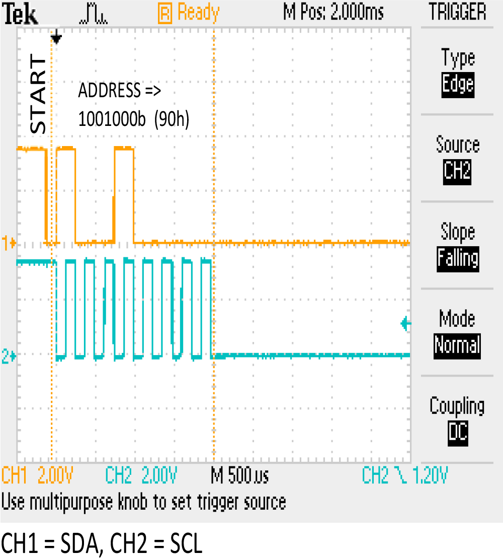
bis.w #UCTXSTT, &UCB0CTLW0 ; I2C START+ADDRESS
mov.w #0x00AA, UCB0TXBUF ; Command DS1621 (Read Temperature)
bis.w #UCTXSTP, &UCB0CTLW0 ; I2C STOP
If I have a program in steps, then the I2C bus works!
There is a “partially” write cycle of the I2C bus in 2 stages
bis.w #UCTXSTT, &UCB0CTLW0 ; I2C START+ADDRESS
mov.w #0x00AA, UCB0TXBUF ; Command DS1621 (Read Temperature)
bis.w #UCTXSTP, &UCB0CTLW0 ; I2C STOP
or
bis.w #UCTXSTT, &UCB0CTLW0 ; I2C START+ADDRESS
mov.w #0x00AA, UCB0TXBUF ; Command DS1621 (Read Temperature)
bis.w #UCTXSTP, &UCB0CTLW0 ; I2C STOP
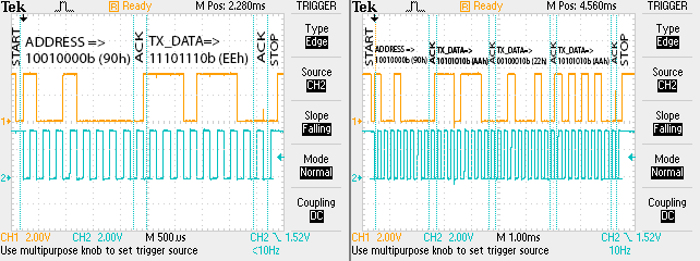
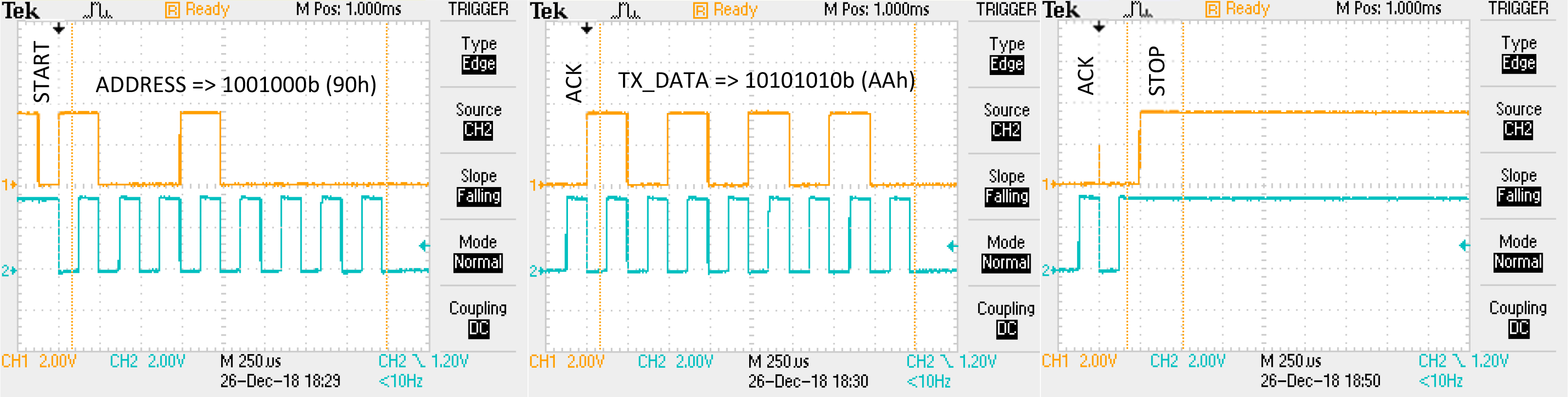
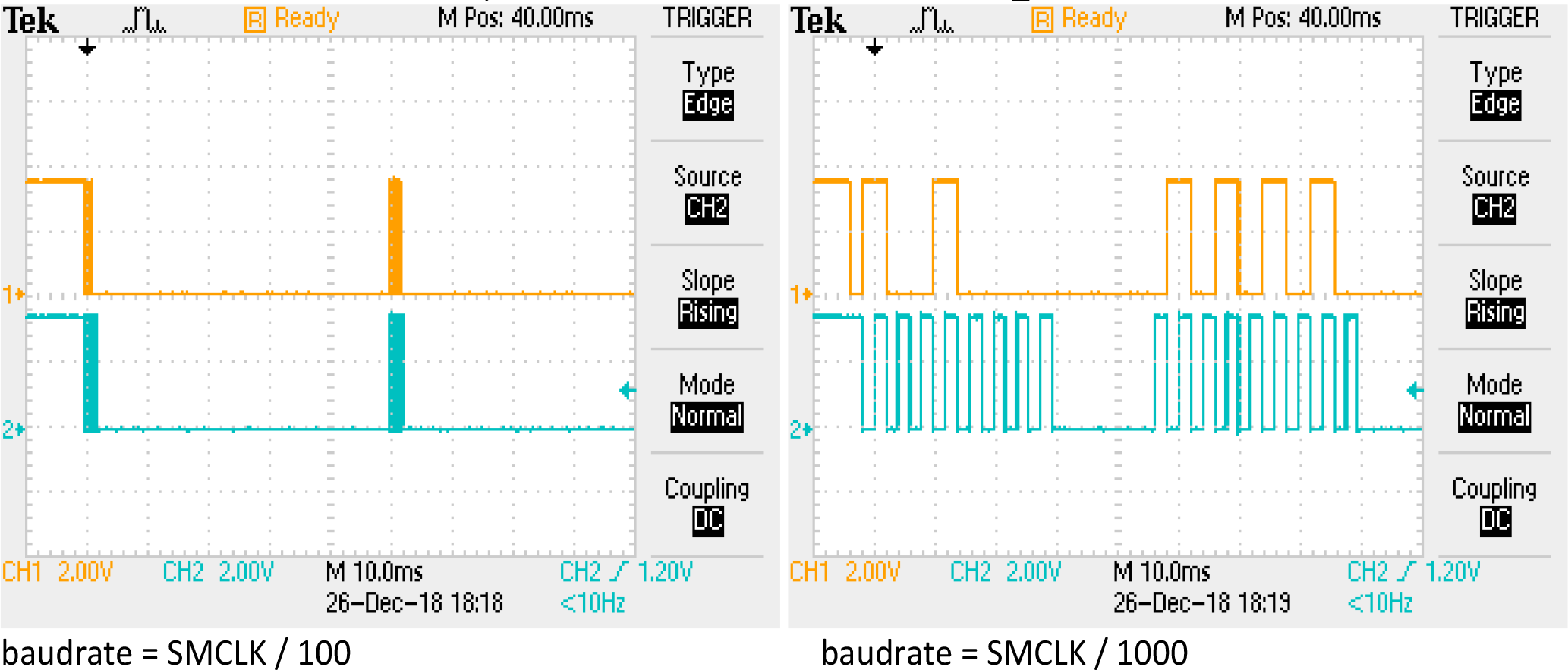
then after START + ADDRESS, ACK + TX_DATA appears in 50ms intervals regardless of baudrate.
Cycle recording of several bytes on the I2C bus is not possible with a partial step by step debugging in 2 stages.
bis.w #UCTXSTT, &UCB0CTLW0 ; START+ADDRESS
mov.w #0x00AA, UCB0TXBUF ; ACK+Command DS1621 (Read Temperature)
mov.w #0x00EE, UCB0TXBUF ; ACK+Command DS1621 (Initiates temperature conversion)
mov.w #0x0022, UCB0TXBUF ; ACK+Command DS1621 (Halts temperature conversion)
mov.w #0x00AA, UCB0TXBUF ; ACK+Command DS1621 (Read Temperature)
bis.w #UCTXSTP, &UCB0CTLW0 ; ACK+STOP
or
bis.w #UCTXSTT, &UCB0CTLW0 ; I2C START+ADDRESS
mov.w #0x00AA, UCB0TXBUF ; ACK+Command DS1621 (Read Temperature)
mov.w #0x00EE, UCB0TXBUF ; ACK+Command DS1621 (Initiates temperature conversion)
mov.w #0x0022, UCB0TXBUF ; ACK+Command DS1621 (Halts temperature conversion)
mov.w #0x00AA, UCB0TXBUF ; ACK+Command DS1621 (Read Temperature)
bis.w #UCTXSTP, &UCB0CTLW0 ; ACK+STOP
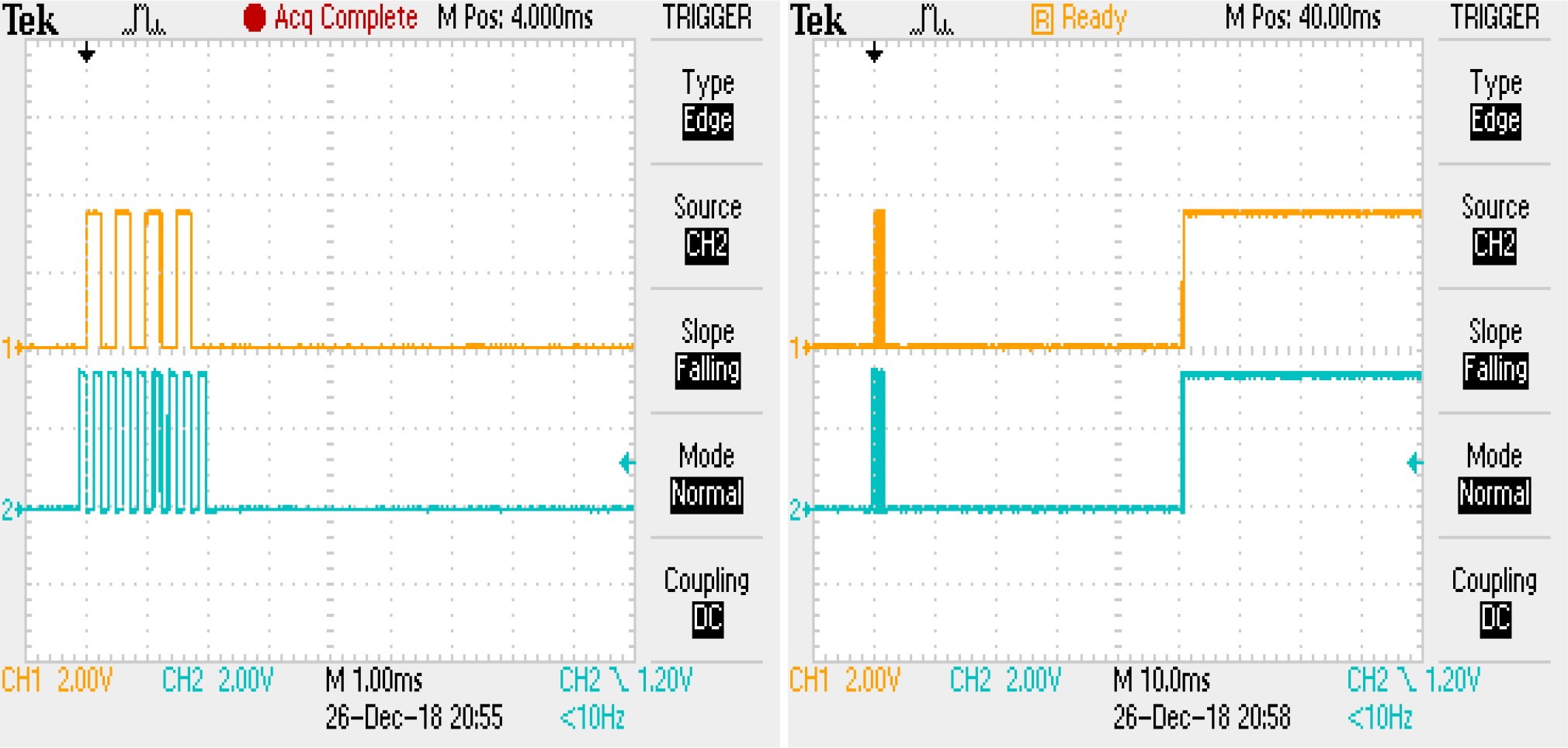
only ACK + 1 byte of data + is transmitted with the same interval of 50 ms appears on the NACK + STOP bus
If you pre-set the data in the register UCB0TXBUF and then in one command to set the bits START + STOP
mov.w #0x00AA, UCB0TXBUF ; Command DS1621 (Read Temperature)
bis.w #UCTXSTT+UCTXSTP, &UCB0CTLW0 ; I2C START+ADDRESS
START + ADRESS + ACK + STOP appear on the bus I2C.

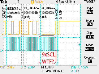
- Why MASTER does not generate ACK after transmitting every 8 bits of data as it is supposed by the I2C protocol and forms it before transmitting the next state (TX_DATA and STOP)?
- Why does the I2C automaton "hang" 50 ms?
- Why does the I2C automaton refuse to perform the bus cycle without step-by-step mode (Analysis of the UCBBUSY bit did not lead to the result)?
- How to transfer several data bytes in 1 write cycle in SLAVE?
Batch code execution causes only the first byte to be read!
bis.w #UCTXSTT, &UCB0CTLW0 ; I2C START+ADDRESS+RX_DATA
mov.w UCB0RXBUF, R7
bis.w #UCTXSTP, &UCB0CTLW0
mov.w UCB0RXBUF, R8 ; ACK+NACK+STOP

In the step-by-step execution of the
bis.w #UCTXSTT, & UCB0CTLW0
command in the debugger, it calls START + ADDRES + ACK + RX_DATA (16bit), while the UCB0RXBUF register (slau445h.pdf page 655) accepts only 8 low bits!
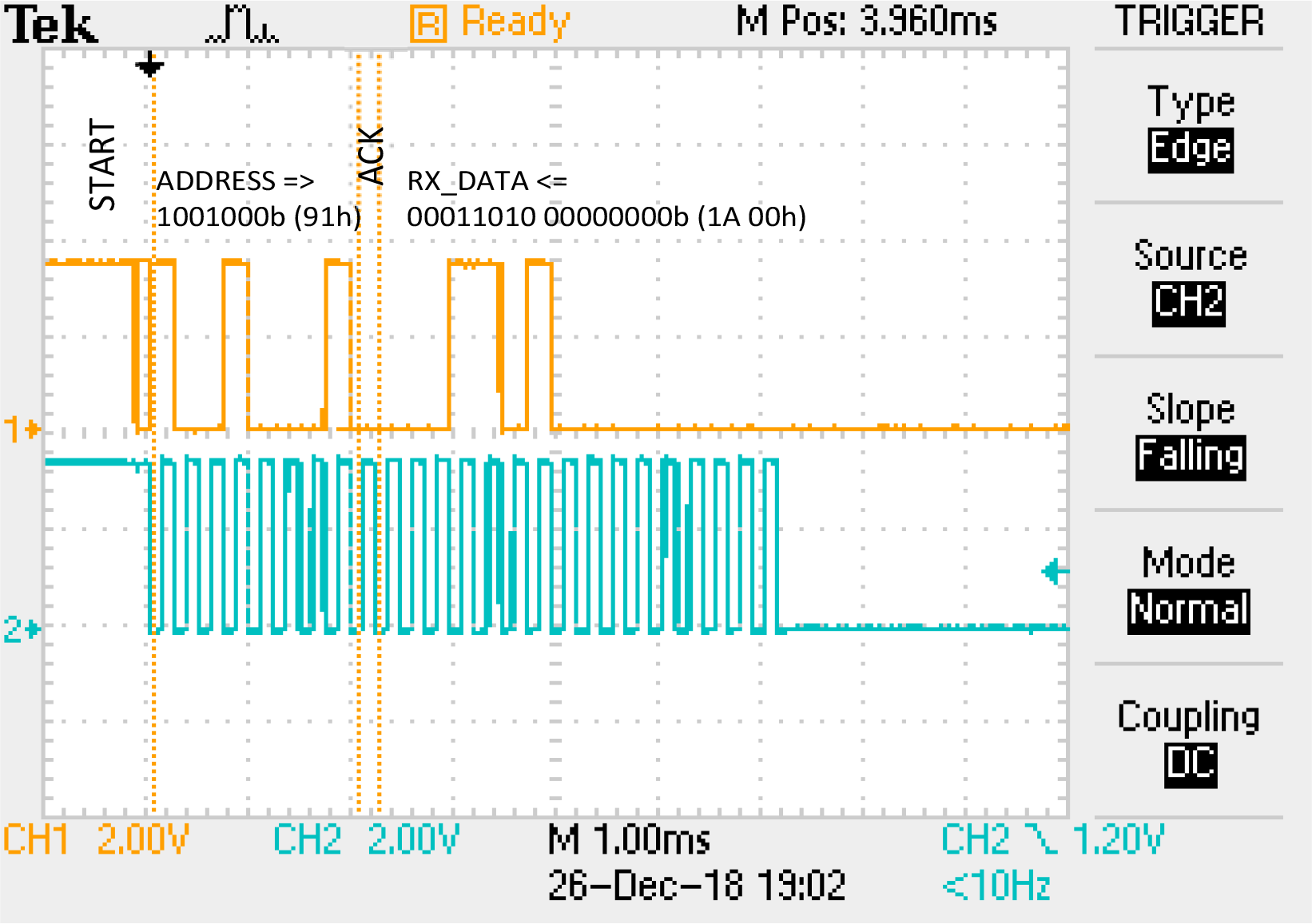
Read register UCB0RXBUF causes ACK + RX_DATA (8 bits) on the bus
mov.w UCB0RXBUF, R7
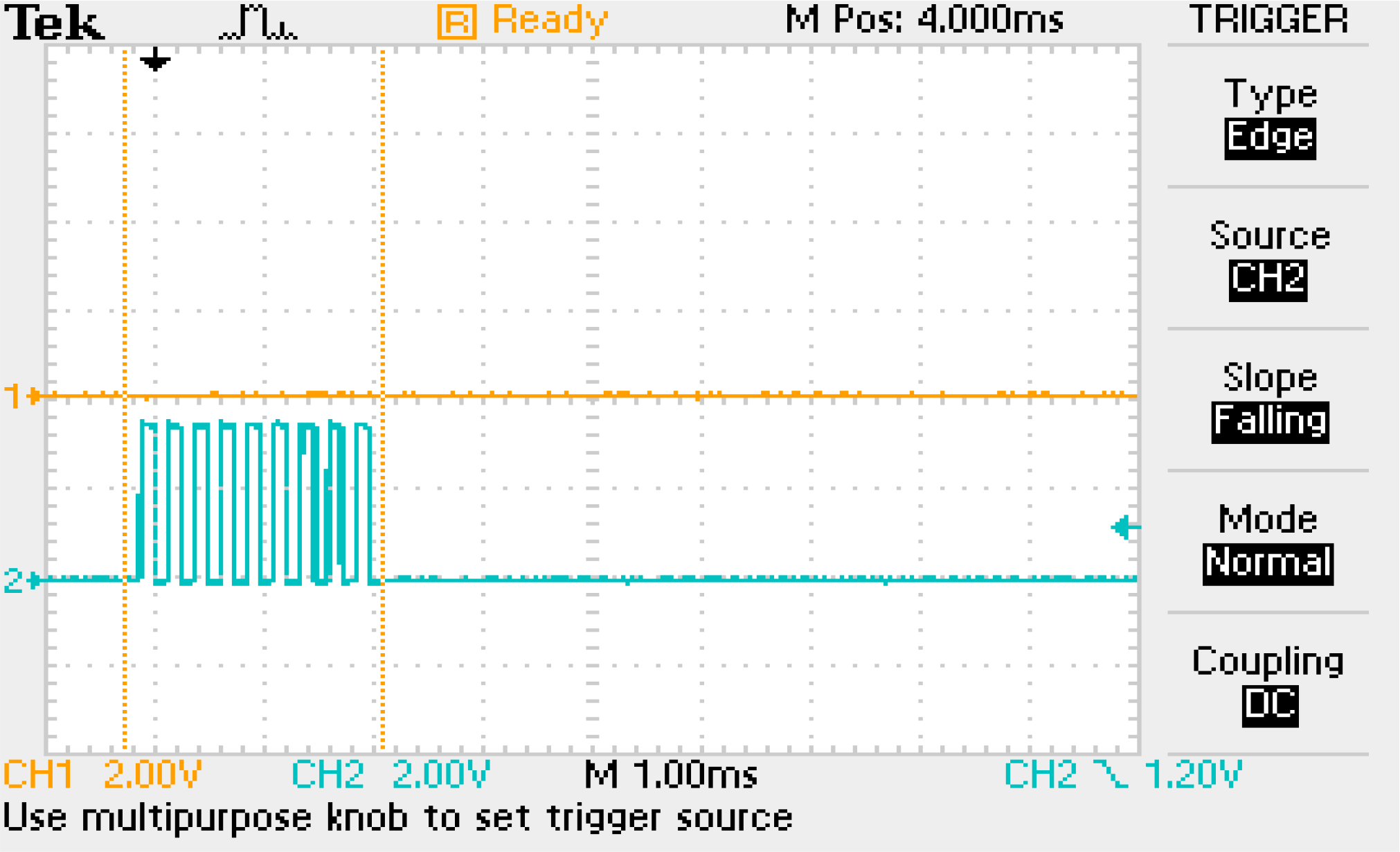
Read register command UCB0RXBUF when the #UCTXSTP bit is set causes ACK + NACK + STOP
bis.w #UCTXSTP, & UCB0CTLW0
mov.w UCB0RXBUF, R7 ; ACK + NACK + STOP

Running
bis.w # UCTXSTT + UCTXSTP, & UCB0CTLW0
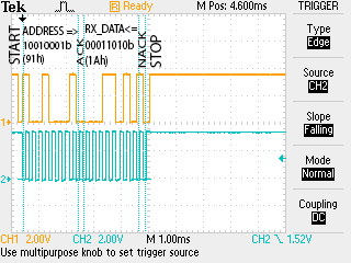
causes a read cycle of 8 data bits START + ADDRESS + ACK + RX_DATA + NACK + STOP
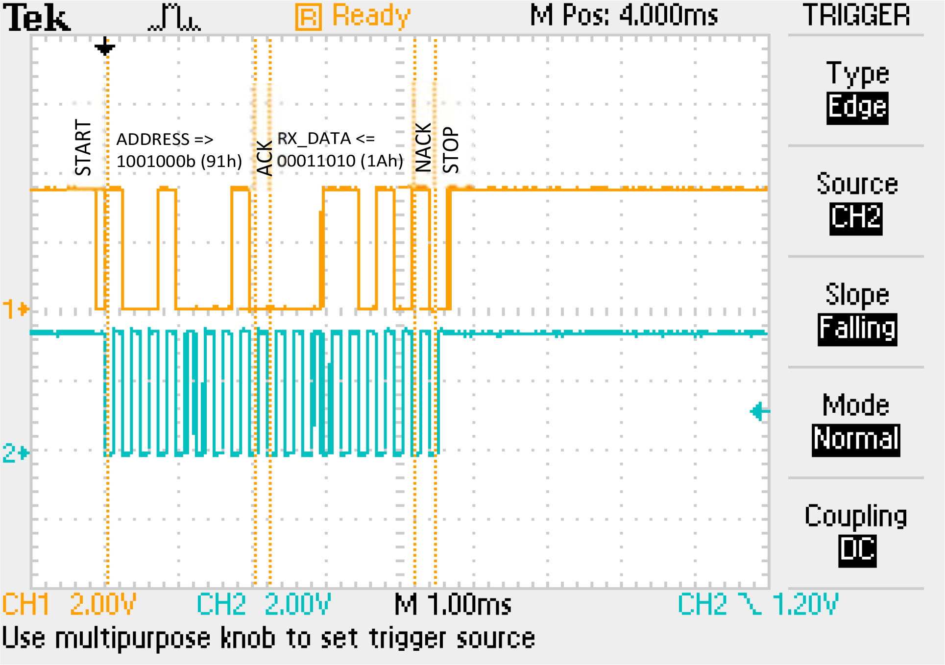
How to read a few bytes of data?
IAR WorkBench ASM code:
;-------------------------------------------------------------------------------
; CPU: MSP430FR2433IRGER
;-------------------------------------------------------------------------------
; I2C adress:
; #090h - DS1621 (W)
; #091h - DS1621 (R)
; UCB0I2CSA = #048h
;-------------------------------------------------------------------------------
#include "msp430.h" ; #define controlled include file
RSEG CSTACK ; Define stack segment
RSEG CODE
;-------------------------------------------------------------------------------
RESET mov.w #SFE(CSTACK),SP ; Initialize stackpointer
StopWDT mov.w #WDTPW+WDTHOLD,&WDTCTL ; Stop watchdog timer
// Configure GPIO
BIS.b #BIT2+BIT3,P1SEL0 ; I2C pins
BIC.b #BIT2+BIT3,&P1DIR
bic.w #LOCKLPM5,PM5CTL0 ; Unlock I/O pins
// Configure USCI_B0 for I2C mode
bis.w #UCSWRST, &UCB0CTLW0
bis.w #UCMST, &UCB0CTLW0 ; I2C Master mode
bis.w #UCMODE_3, &UCB0CTLW0 ; eUSCI_B mode = I2C
mov.w #0x0100, UCB0BRW ; baudrate = SMCLK / 100
bic.w #UCSWRST, &UCB0CTLW0 ;
wait1 bit.w #UCBBUSY,&UCB0STATW ; wait until I2C module has finished all operations
JC wait1
// WIRITE I2C
mov.w #0x0048, UCB0I2CSA ; I2C slave address = DS1621
bis.w #UCTR, &UCB0CTLW0 ; I2C=TX
bis.w #UCTXSTT, &UCB0CTLW0 ; START+ADDRESS
mov.w #0x00AA, UCB0TXBUF ; ACK+Command DS1621 (Read Temperature)
mov.w #0x00EE, UCB0TXBUF ; ACK+Command DS1621 (Initiates temperature conversion)
// Pause
nop
// ----
mov.w #0x0022, UCB0TXBUF ; ACK+Command DS1621 (Halts temperature conversion)
mov.w #0x00AA, UCB0TXBUF ; ACK+Command DS1621 (Read Temperature)
bis.w #UCTXSTP, &UCB0CTLW0 ; ACK+STOP
// READ I2C
bic.w #UCTR, &UCB0CTLW0 ; I2C=RX
bis.w #UCTXSTT+UCTXSTP, &UCB0CTLW0 ;START+ADDRESS+RX_DATA
mov.w UCB0RXBUF, R7
bis.w #UCTXSTT, &UCB0CTLW0 ; I2C START+ADDRESS+RX_DATA
mov.w UCB0RXBUF, R7
bis.w #UCTXSTP, &UCB0CTLW0
mov.w UCB0RXBUF, R8 ; ACK+NACK+STOP
JMP $ ; jump to current location '$'
; (endless loop)
;-------------------------------------------------------------------------------
COMMON INTVEC ; Interrupt Vectors
;-------------------------------------------------------------------------------
ORG RESET_VECTOR ; Reset Vector
DW RESET
END