This thread has been locked.

If you have a related question, please click the "Ask a related question" button in the top right corner. The newly created question will be automatically linked to this question.

MSP430G2553: Issue With MSP430G2553 USCI module interrupts after BSL programming

Part Number: MSP430G2553
Other Parts Discussed in Thread: MSP-FET

Hello,

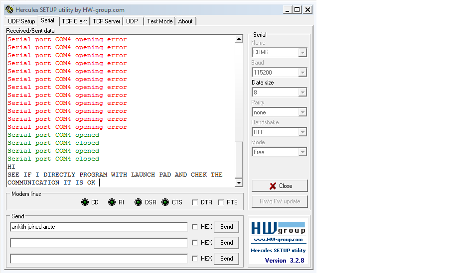
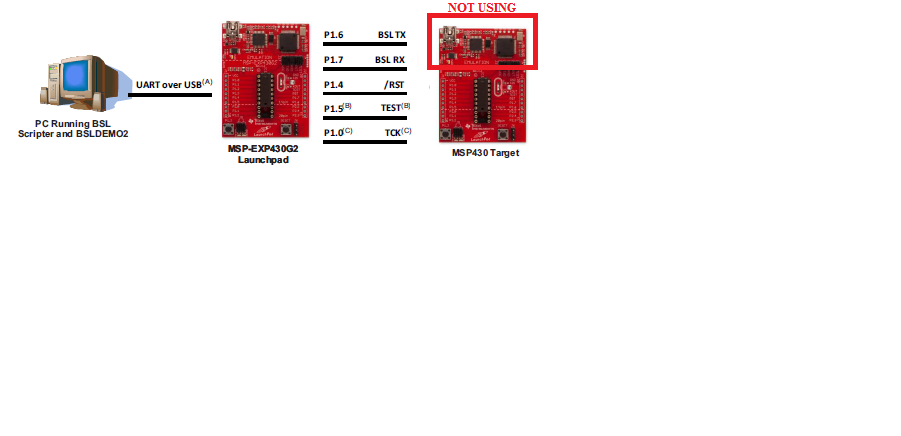
I am trying BSL programming for MSP430G2553 using the app note slaa535a.pdf and LPAD_BSL_INTERFACE firmware downloaded from Texas website. I’m able to successfully program led blinky example code to 2553 chip and it works. My issue is when I program the UART loopback example code using bsl programming, it programs successfully but code is not working as expected. Below is the UART example code (I am using launch pad for testing).

//******************************************************************************

//   MSP430G2xx3 Demo - USCI_A0, 115200 UART Echo ISR, DCO SMCLK

//

//   Description: Echo a received character, RX ISR used. Normal mode is LPM0.

//   USCI_A0 RX interrupt triggers TX Echo.

//   Baud rate divider with 1MHz = 1MHz/115200 = ~8.7

//   ACLK = n/a, MCLK = SMCLK = CALxxx_1MHZ = 1MHz

//

//               MSP430G2xx3

//             -----------------

//         /|\|             XIN|-

//         | |                 |

//         --|RST         XOUT|-

//           |                 |

//          |     P1.2/UCA0TXD|------------>

//           |                 | 115200 - 8N1

//           |     P1.1/UCA0RXD|<------------

//

//   D. Dang

//   Texas Instruments Inc.

//   February 2011

//   Built with CCS Version 4.2.0 and IAR Embedded Workbench Version: 5.10

//******************************************************************************

#include "msp430g2553.h"


void main(void)

{

WDTCTL = WDTPW + WDTHOLD;                 // Stop WDT

BCSCTL1 = CALBC1_1MHZ;                   // Set DCO

DCOCTL = CALDCO_1MHZ;

P1SEL = BIT1 + BIT2 ;                     // P1.1 = RXD, P1.2=TXD

P1SEL2 = BIT1 + BIT2;                    

UCA0CTL1 |= UCSSEL_2;                     // SMCLK

UCA0BR0 = 8;                             // 1MHz 115200

UCA0BR1 = 0;                             // 1MHz 115200

UCA0MCTL = UCBRS2 + UCBRS0;               // Modulation UCBRSx = 5

UCA0CTL1 &= ~UCSWRST;                     // **Initialize USCI state machine**

IE2 |= UCA0RXIE;                         // Enable USCI_A0 RX interrupt


__bis_SR_register(LPM0_bits + GIE);       // Enter LPM0, interrupts enabled

}


// Echo back RXed character, confirm TX buffer is ready first

#pragma vector=USCIAB0RX_VECTOR

__interrupt void USCI0RX_ISR(void)

{

while (!(IFG2&UCA0TXIFG));               // USCI_A0 TX buffer ready?

UCA0TXBUF = UCA0RXBUF;                   // TX -> RXed character

}


Before BSL programming this code is tested and it works when I program using ccs ide (I am getting UART TX and RX interrupts in debug mode). Same code when I program using BSL it is not working as I don’t receive any character in HyperTerminal.

To debug this I approached two methods.

  1. In the same chip, reprogram led blinky code using BSL approach, code is working.
  2. Now when I reprogram the same chip again with UART loop back example code using CCS ide in debug mode, I am not getting UART TX and RX interrupts at all (looks like somehow UART interrupts are permanently disabled when we do BSL programming)

Can somebody please help me to debug this issue.

Thank you,

Best regards,

ANKITH BR


  • Hi

    How the hardware connection is? Do you have a MSP-FET or BSL rocket?Can you get the UART feedback character in HyperTerminal using ccs IDE debug mode?

    Gary
  • Hi Gary,

    Thanks a lot for your support. To answer your question,we are NOT using BSL rocket  for programming. We are using the flow described in the document - "slaa535a" which uses MSP430 launch pad for BSL programming.

    In order to ensure that there is no issue with our example code, we have used the traditional approach of progamming the IC within the launch pad board using CCS. We confirm that our code works and as you can see below, there is communication betwen the IC and Hyperterminal. However, if we attempt to flash the same code using BSL, we run into issues specific to UART/USCI functionality. Once we flash the chip using BSL, it fails to communicate with hyper terminal even after attempting to reflash the same with CCS again. In other words, we can never get the IC to communicate over its hardware UART ever.

    1) If we program a new MSP430G2553 chip with CCS, we are able to communicate b/w the IC and Hypterminal. Please see below for reference

    2) Now we have tried to program this IC with the same code (after dumping the corresponding .TXT file) using MSP430 BSL flow as described in slaa535a. This runs successfully but the IC fails to communicate with Hyperterminal as shown below

     3)Please find the hardware setup details shared below. Kindly note that using this flow, we are able to successfully program any msp430 example code that does not use UART/USCI functionality. The issue arises only when this flow is attempting to flash a program that uses hardware UART/USCI functionality only. I hope this explains the issue better. Please advise if you need any further details.


    Best Regards,

    Ankith

  • Hi Ankith

    I think I have know your problem. I think you should test the code like this. When you finish download the UART loopback example code connect the MSP430 target board with PC using the USB. Then you can try to send characters in HyperTerminal to see if it can works.

    Gary
  • HI gary

    When you finish download the UART loopback example code connect the MSP430 target board with PC using the USB. Then you can try to send characters in HyperTerminal to see if it can works.
    this i already tried it,it doesn't work.
    their is a issue with BSL programming specific to UART.

    Thank you,

    Best regards,
    ANKITH BR
  • Hi

    You can use the the FET-PRO430 (www.elprotronic.com/products to read the code in the flash when you finish download the code and compared two download ways results.

    Gary
  • If you are saying that BSL flashing makes the chip unusable for any UART purpose, even attempting to reflash it with CSS, then it may be that your BSL session is doing a mass erase that is wiping out your calibration data in INFOA, which would make it virtually impossible to get the right baud rate thereafter.

    I would just say that I have tested the 535.pdf method, and it seemed to work fine.  But if you send a bad password in BSL,  it will mass erase the chip, including INFOA, unless you have protected against that with the proper values stored at 0xFFDE.

    This explanation could be tested by reading in the contents of INFO memory of one of the ruined chips using JTAG and the command line MSP430Flasher.exe program (or maybe CCS will do that).  If it's all FFs, then that's the explanation.  But if the calibration data is still there, then I don't know.  There really isn't anything else you can to to the G2553 to ruin it.

    Another test would be to copy the INFOA contents of a brand new chip to your computer as a .hex file, then go through the process of destroying it with BSL, then restore INFOA using Flasher JTAG, and see if it is working again.

    I don't know what software you are using for BSL, but if it's BSLDEMO, I would be interested in seeing your BSL flashing command line.

  • hi George Hug,

    Thanks for the reply and your suggestions. 

    We are following the exact procedure explained in slaa535a datasheet and downloaded slaa535a.zip file from this URL: http://www.ti.com/lit/zip/slaa535

    Below is the BSL flashing command line in the test.bat 

    ..\Exe\BSLDEMO2.exe -cCOM4 -m1 +epvrw BLINK_MSP430G2553.txt

    In the above command line we just edited the comport number. When we run this batch file below is the screen shot of flashing process.

    with this information can please suggest any changes required in command line so that it will not erase the INFO memory of MSP430-G2553.

    Thank You

    Ankith BR

  • Hi Ankith BR,

    Your command line:

    "BSLDEMO2.exe -cCOM4 -m1 +epvrw BLINK_MSP430G2553.txt"

    includes the default program flow specifier +epvrw.  The "e" specifier is a Mass Erase, and your screen capture shows this command being carried out.

    But there is also an "a" specifier which can be added, which will copy INFOA to your computer before the Mass Erase, and restore it after.  However, this process works only if you provide the correct password. The password is the current contents of the interrupt vector block of the G2553.  That is 32 bytes found at 0xFFE0 - 0xFFFF, and is provided to BSLDEMO as a TI-TXT file, which you might name PW.TXT.  So the command line would then read (changes in bold):

    "BSLDEMO2.exe -cCOM4 -m1 -pPW.TXT +aepvrw BLINK_MSP430G2553.txt"

    A new G2553 which is completely blank except for INFO memory calibration data will have a PW.TXT with this contents:

    @FFE0
    FF FF FF FF FF FF FF FF FF FF FF FF FF FF FF FF
    FF FF FF FF FF FF FF FF FF FF FF FF FF FF FF FF
    q

    It is possible that BSLDEMO will automatically provide that password to the chip if you don't specify a password file.  I just don't remember.  But it's safer to provide the file.

    The G2553 which came with my Launchpad had an LED blink and temperature demonstration firmware pre-installed.  Its PW.TXT looks like this:

    @FFE0
    FF FF FF FF 14 FC FF FF FF FF 5E FD FF FF FF FF
    0E FD E6 F9 28 FD FF FF FF FF FF FF FF FF C2 FC
    q

    And any firmware that you flash will produce a different vector block.  You may be able to find that in the HEX or TI-TXT file that you flash to the chip.  Or it may be that CCS has a way to automatically generate a password file - the TI guys here would know more about how that can be done.  In any  case, you cannot use BSL for the G2553 unless you have a current valid password file.  If you provide a bad password, or no password, the chip will be mass erased, incuding all of INFO memory.  An exception can be found in Section 2.7 of slau319t.pdf,  which provides a way to avoid the mass erase on a bad password (but not on a +e specifier).

    In my opinion this erasure of calibration data for any reason related to the password was not a good design decision by TI.  And later chips aren't so draconian.  But as it stands for the G2553 and similar BSLs, you have to adopt extraordinary measures to avoid living on the edge of disaster (calibration data erasure).  One method is to use an intermediate jump table for the interrupt vectors, so the vectors always point to the jump table entries, and only the jump table contents change from one firmware version to the next. The password never changes.  Another method is to enter BSL through firmware in a way that makes it impossible for BSL to erase INFO memory.  But without doing something like that, you have to be able to produce the current valid password file for any G2553 you flash with BSL.

    Hope this will help.

  • HI George Hug ,

    we have fallowed your inputs and we are successful in flashing the code using BSL without erasing the info memory and code works as excepted.

    thanks a lot for your valuable inputs and the issue is resolved.  

    once again thank you George Hug


    best regards 

    Ankith BR


  • You are quite welcome.  I'm glad it's working now.

    I know that the slaa535 method is now quite old, but you should not have been offered a test script in TI's zip file specifically for the G2553 that wipes out your calibration data, and would do the same to anyone else who ran it as is.  And I suspect that may be true for test scripts for other parts.  There are nine other scripts containing "+epvrw", and any of those with the same calibration data situation would have the same problem.

**Attention** This is a public forum