This thread has been locked.

If you have a related question, please click the "Ask a related question" button in the top right corner. The newly created question will be automatically linked to this question.

MSP430FR5994: Lanchpad SVSH Counter Read Failure (Assembler Code Sample)

Part Number: MSP430FR5994

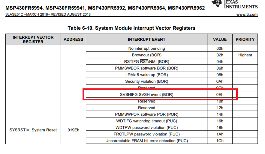
When running the Launchpad in active mode (using the supercap) the RTC counters does not read correctly if a SVSH was triggered.

;--COPYRIGHT--,BSD_EX
;  Copyright (c) 2012, Texas Instruments Incorporated
;  All rights reserved.
;
;  Redistribution and use in source and binary forms, with or without
;  modification, are permitted provided that the following conditions
;  are met:
;
;  *  Redistributions of source code must retain the above copyright
;     notice, this list of conditions and the following disclaimer.
;
;  *  Redistributions in binary form must reproduce the above copyright
;     notice, this list of conditions and the following disclaimer in the
;     documentation and/or other materials provided with the distribution.
;
;  *  Neither the name of Texas Instruments Incorporated nor the names of
;     its contributors may be used to endorse or promote products derived
;     from this software without specific prior written permission.
;
;  THIS SOFTWARE IS PROVIDED BY THE COPYRIGHT HOLDERS AND CONTRIBUTORS "AS IS"
;  AND ANY EXPRESS OR IMPLIED WARRANTIES, INCLUDING, BUT NOT LIMITED TO,
;  THE IMPLIED WARRANTIES OF MERCHANTABILITY AND FITNESS FOR A PARTICULAR
;  PURPOSE ARE DISCLAIMED. IN NO EVENT SHALL THE COPYRIGHT OWNER OR
;  CONTRIBUTORS BE LIABLE FOR ANY DIRECT, INDIRECT, INCIDENTAL, SPECIAL,
;  EXEMPLARY, OR CONSEQUENTIAL DAMAGES (INCLUDING, BUT NOT LIMITED TO,
;  PROCUREMENT OF SUBSTITUTE GOODS OR SERVICES; LOSS OF USE, DATA, OR PROFITS;
;  OR BUSINESS INTERRUPTION) HOWEVER CAUSED AND ON ANY THEORY OF LIABILITY,
;  WHETHER IN CONTRACT, STRICT LIABILITY, OR TORT (INCLUDING NEGLIGENCE OR
;  OTHERWISE) ARISING IN ANY WAY OUT OF THE USE OF THIS SOFTWARE,
;  EVEN IF ADVISED OF THE POSSIBILITY OF SUCH DAMAGE.
;
; ******************************************************************************
;
;                        MSP430 CODE EXAMPLE DISCLAIMER
;
;  MSP430 code examples are self-contained low-level programs that typically
;  demonstrate a single peripheral function or device feature in a highly
;  concise manner. For this the code may rely on the device's power-on default
;  register values and settings such as the clock configuration and care must
;  be taken when combining code from several examples to avoid potential side
;  effects. Also see www.ti.com/grace for a GUI- and www.ti.com/msp430ware
;  for an API functional library-approach to peripheral configuration.
;
; --/COPYRIGHT--
;******************************************************************************
;  MSP430FR59x Demo - Toggle P1.0 using software
;
;  Description: Toggle P1.0 using software.
;  ACLK = n/a, MCLK = SMCLK = TACLK = default DCO = ~625 KHz
;
;           MSP430FR5969
;         ---------------
;     /|\|               |
;      | |               |
;      --|RST            |
;        |               |
;        |           P1.0|-->LED
;
;   Tyler Witt/ P. Thanigai
;   Texas Instruments Inc.
;   August 2012
;   Built with Code Composer Studio V5.5
;******************************************************************************
;-------------------------------------------------------------------------------
            .cdecls C,LIST,"msp430.h"       ; Include device header file
;-------------------------------------------------------------------------------
            .def    RESET                   ; Export program entry-point to
                                            ; make it known to linker.
;-------------------------------------------------------------------------------
            .global _main
            .global __STACK_END
            .sect   .stack                  ; Make stack linker segment ?known?

            .text                           ; Assemble to Flash memory
            .retain                         ; Ensure current section gets linked
            .retainrefs

;-------------------------------------------------------------------------------
; Main code here
;-------------------------------------------------------------------------------
_main
RESET       mov.w   #__STACK_END,SP         ; Initialize stackpointer
StopWDT     mov.w   #WDTPW+WDTHOLD,&WDTCTL  ; Stop WDT

UnlockGPIO  bic.w   #LOCKLPM5,&PM5CTL0      ; Disable the GPIO power-on default
                                            ; high-impedance mode to activate
                                            ; previously configured port settings


;-------------------------------------------------------------------------------
; SVSH reset code here
;-------------------------------------------------------------------------------
			cmp.b 	&IV,	&SYSRSTIV  ; Check if reset is SVSH
  			jne SKIPSVSH
  			mov.b 	&RTCCNT1,	&CNT1
  			mov.b 	&RTCCNT2,	&CNT2
  			mov.b 	&RTCCNT3,	&CNT3
  			mov.b 	&RTCCNT4,	&CNT4
  			add.w	#1,	&RESETCNT
SKIPSVSH:

            mov.b   #0x10,	&PJSEL0			; PJ SEL0 lfxt
  			mov.b	#0xA5,	&RTCCTL0_H		; unlock
  			mov.b	#RT1SSEL,	&RTCCTL1	; setup counter mode.
			mov.b	#0x1C,  &RTCPS0CTL
			mov.b	#RT1SSEL+RT1PSDIV+RT1IP,	&RTCPS1CTL
			bic.b	#RTCHOLD,	&RTCCTL1	; clear the RTCHOLD and bit to start the counter.
  			mov.b	#0xA5,	&RTCCTL0_H		; lock


SetupP1     bis.b   #BIT0,&P1OUT            ; Clear P1.0 output latch for a defined power-on state
            bis.b   #BIT0,&P1DIR            ; Set P1.0 to output direction

MainLoop:
			nop
			jmp MainLoop
			nop

;-------------------------------------------------------------------------------
; Variable definitions
;-------------------------------------------------------------------------------
			.text
CNT1		.byte 0xFF
CNT2		.byte 0xFF
CNT3		.byte 0xFF
CNT4		.byte 0xFF
RESETCNT	.word 0xFFFF
IV			.word 0x000E
.end
                                            

;-------------------------------------------------------------------------------
; Stack Pointer definition
;-------------------------------------------------------------------------------
            .global __STACK_END
            .sect   .stack
            
;-------------------------------------------------------------------------------
; Interrupt Vectors
;-------------------------------------------------------------------------------
            .sect   ".reset"                ; MSP430 RESET Vector
            .short  RESET
 

and here are the results of the diagnostic variables:

CNT1
3021
CNT3
0002
RESETCNT
0000
IV
000E

  • Hi,

    Thanks for share your code. I will test it and feedback you early next week.
  • Hi ctm,

    I'm sorry to reply late. But I'm too busy to take time to test your code in past few days. I will take chance to check your issue tomorrow and reply you then.
  • Hi ctm,

    After reviewing you code, I'm confused the time you read and save the RTCCNTx. You read and save the RTC count values after the SVSHIFG SVSH event (BOR). However, the RTC count registers shouldn't contain the value after a BOR, which mean the count values would be reset or some dummy value after a BOR reset.

    I will double confirm with our development team for the value of the RCTCNTx after a BOR event.
  • I read the RCTCNTx after the SVSH event but before the BOR.

    The issue is if the supercap discharges, everything can be kept running until the SVSH event. Now the RCTCNTs are saved to FRAM to be restored when a normal power-up happens. (I can confirm that the save does happen before the BOR.)
  • Hi,

    I'm confused with your assembly code. You just check the SYSRSTIV and do the saving at beginning of your code, which could just be run after a new power up or PUC/BOR reset. However, all these events could let RTCCNTx not containing the value.

  • Please read the documentation.

    Normal reset bypasses the code you marked. You can check this in the debugger.

    When the supercap discharges three resets will occur.

    1. SVSH - (here we try to read and save the counter)
    2. BOR - final power-down
    3. Power-up - to read the saved information.

    Only 1 will execute the code marked.

    c-:

  • Hi ctm,

    I would make it clear for your code of reading and saving the RTCCNTx value. These codes were run after checking the SYSRSTIV with SVSHIFG SVSH event (BOR) condition(0Eh)

    Please be noted that the SVSH event will trigger a BOR reset, which means the 1&2 reset conditions from your last reply are actually the same one. You can find the detailed description on section "1.2 System Reset and Initialization" and "2.2.2.1 SVS Thresholds" of the device User's Guide.

    So, the codes which read and save the RTCCNTx value will always be run after a BOR reset, which been triggered by an SVSH event.

  • I can confirm that there are two resets: 1. the SVSH reset and then 2. the BOR reset.

    The reason for two resets is as follows:

    When it is run from battery or supercap the SVSH reset normally used to save important parameters such as clock/counter to FRAM. The SVSH reset triggers a BOR.

    (Is it possible to escalate this matter?)

    c-:
  • Hi ctm,

    There should be some misunderstanding with our discussion.

    You may need to refer to section "1.2 System Reset and Initialization" of the device User's Guide. The device has 3 types of system reset, which are a brownout reset (BOR), a power-on reset(POR), and a power-up clear (PUC). And an SVSH low condition will trigger a BOR. I can't find any description for an individual SVSH reset in the User's Guide. If you could find any information, please share me.

    As we discussed for a long time, I would give you some suggestion for your application.
    1. You may clear the SVSHE bit to disable the Supply Voltage Supervisor for triggering a BOR reset. Then you need to monitor the SVSHIFG flag in a while loop and store the RTC value when the flag is set.
    2. You may monitor the DVCC by ADC and store the RTC value when the DVCC drops below the threshold you set, before the BOR reset occurs.
  • I now know where the issue came from - here is the FR5994 manual:

    The RTC_C module registers are shown in Table 29-2. This table also shows which registers are key protected and which are retained during LPM3.5. The registers that are retained during LPM3.5 and given with a reset value are not reset on POR. Registers that are not retained during LPM3.5 must be restored after exit from LPM3.5.

    As you quoted, SVSH causes a BOR on the FR5994.

    Here is the F5338 manual:

    If DVCC falls below the SVSH level, SVSHIFG (SVSH interrupt flag) is set. If DVCC remains below the SVSH level and software attempts to clear SVSHIFG, it is immediately set again by hardware. If the SVSHPE (SVSH POR enable) bit is set when SVSHIFG gets set, a POR is generated.

    On the F5338 SVSH causes a POR - and then the counters are not reset.

    I actually think the F5338 way of doing things are far better as it will allow a counter save to FRAM just before the final BOR.  Doing a SVSH BOR reset defeats the object.

    May I suggest that this be includes as a feature upgrade?

    Just to confirm the use of SVSH in waking up from LPM3.5.  The manual states:

    Note, the "wakeup" due to a supply failure would not be flagged as a LPMx.5 wake-up but as a SVS reset event.

    and

    A BOR is a device reset. A BOR is generated only by the following events:

    -

    - Wake-up event from LPMx.5 (that is, LPM3.5 or LPM4.5) mode

    - SVSH low condition, when enabled (see the PMM and SVS chapter for details)

    and in the case of a LPM3.5 SVSH event the registers is also lost?  Refer Table 29-2. RTC_C Registers retained from LPM3.5.

**Attention** This is a public forum