This thread has been locked.
If you have a related question, please click the "Ask a related question" button in the top right corner. The newly created question will be automatically linked to this question.
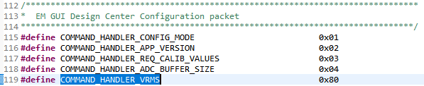
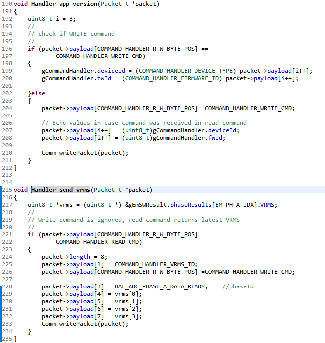
Hi team, in the reference code generated by EMDC for the i2040 sub metering EVM, there is aprovision for the I2C interface also. Using the MACRO i have enabled it and it did build without errors. Please advice have we tested the I2C on this EVM or not? if yes then please share the I2C host example it was tested with.
Hello Abhed,
The code generated by EMDC only supports UART as provided. Unfortunately, we do not have code with I2C support out-of-the-box. However, we encourage users to modify this code according to their specific application. While the communication type and protocol may change, you can still leverage the EMDC APIs and don't need to focus on how to develop/calculate/measure the metrology parameters.
Please keep in mind that if you change the communication type from UART to I2C, then you won't be able to use the EMDC GUI with that code base. However, you can use the target device with a host device over I2C assuming it supports the same protocol.
Regards,
James
Hi James,
Thanks for the reply. Thanks for clarifying that the I2C interface has not been tested and supported out of box using EMDC with i2040S EVM. I intend to use the EVM on I2C interface ONLY, andneed your help with the same. Please advice do you have any working example of I2C master which you have validated with i2040S EVM? It will be of great help as a time window is a bit short here.
Hello Abhed,
I would recommend referring to our I2C code examples (either register-level or DriverLib) as a starting point. You can find several different examples including I2C Master at the link below.
What's the application here?
Regards,
James
Hi James,
The application is of using i2040 as the metering frontend interfaced on I2C. It was presumed that just becasue the MACRO is defined in the reference code the I2C communication will work out of box. However, that is nto the case as you said.
The reason behind asking you to have a look at it was to save time in gettign well versed with the code and then figuring out the bugs(if any) and fix the code.
I had tested the I2C interace with F5529 LP runnign I2C master but did not see the i2040S responding to the i2C call back function.
Hello,
We have done some testing on our side and seem to have enabled I2C communication in a few steps. Keep in mind that we haven't tested this much and it won't work with the EMDC GUI at the moment. However, you should be able to communicate with the target i20xx device with an I2C master using the same protocol.
Here are the steps we took to achieve this. First, generate your project using EMDC for the MSP430i20xx device. The following changes were made to that code base.
//! \def Serial communication interface selection. Set this to one of the valid //! interfaces or COMM_NONE to disable the COMM module. //! #define COMM_SERIAL_INTERFACE (COMM_I2CSLAVE) //! \def Serial communication interface selection enable definitions //! These are set automatically to include the relevent modules. //! #if (COMM_SERIAL_INTERFACE==COMM_UART) #define UART__ENABLE (true) #define I2CSLAVE__ENABLE (false) #define TIMEOUT__ENABLE (false) #elif (COMM_SERIAL_INTERFACE==COMM_I2CSLAVE) #define UART__ENABLE (false) #define I2CSLAVE__ENABLE (true) #define TIMEOUT__ENABLE (true) #endif
void Timer_startDelayedFunctionTimer(const tFunctionTimer *pFunctionTimer) { Timer_stopDelayedFunctionTimer(); g_pFunctionTimer = pFunctionTimer; HWREG16(FUNCTIONTIMER__PERIPHERAL + OFS_TAxCCTL0) &= ~(CCIFG); HWREG16(FUNCTIONTIMER__PERIPHERAL + OFS_TAxCCTL1) &= ~(CCIFG); //HWREG16(FUNCTIONTIMER__PERIPHERAL + OFS_TAxEX0) = FUNCTIONTIMER__EXDIVIDER; HWREG16(FUNCTIONTIMER__PERIPHERAL + OFS_TAxCTL) = (FUNCTIONTIMER__CLOCK | FUNCTIONTIMER__DIVIDER | MC__CONTINUOUS | TACLR); }
// // Local Function declarations // //***************************************************************************** // //! Initializes GPIOs //! //! \return none // // ***************************************************************************** static void hal_system_GPIOInit(void) { /* P1.6: I2C UCB0SCL & P1.7: I2C UCB0SDA */ GPIO_setAsPeripheralModuleFunctionInputPin(GPIO_PORT_P1, GPIO_PIN6 | GPIO_PIN7, GPIO_PRIMARY_MODULE_FUNCTION); }
//***************************************************************************** // //! \def I2CSLAVE__EUSCI_B_PERIPHERAL defines the MSP430 base address of the //! eUSCI_B instance being used with this I2C slave port. // //! \def I2CSLAVE__ADDRESS defines the I2C bus address associated with this //! device. // //***************************************************************************** #define I2CSLAVE__EUSCI_B_PERIPHERAL (EUSCI_B0_BASE) #define I2CSLAVE__ADDRESS (0x0A)
Now, assuming your host I2C devices uses the correct slave address and same protocol, the communication should work. For our test, we used the EVM430-i2040S and connected to the exposed I2C pins, P1.6 and P1.7, on the J9 header. Looking at the EVM430-i2040S schematic, use J9.1 for P1.7 (UCB0SDA), J9.2 for GND and J9.3 for P1.6 (UCB0SCL).
We sent over this EMDC command packet (hexadecimal format) that tells the target i20xx to start sending data periodically. You can reference the protocol section in the EMDC Technology Guide if you have questions about the protocol. The device sent something back which indicated the communication was working.
55AA06040101010700
Regards,
James
Hi Abhed,
I addition to the I2C Slave changes mentioned above by James, here's an example for the I2C Master using F5529 LP:
//****************************************************************************** // MSP430F552x Demo - USCI_B0, I2C Master multiple byte TX/RX // // Description: I2C master communicates to I2C slave sending and receiving // messages of different length. I2C master will enter LPM0 mode // while waiting for the messages to be sent/receiving using I2C interrupt. // ACLK = NA, MCLK = SMCLK = DCO 16MHz. // // /|\ /|\ // MSP430F5529 4.7k | // ----------------- | 4.7k // /|\ | P3.1|---+---|-- I2C Clock (UCB0SCL) // | | | | // ---|RST P3.0|-------+-- I2C Data (UCB0SDA) // | | // | | // | | // | | // | | // | | // // Texas Instruments Inc. // June 2019 // Built with CCS V9.x //****************************************************************************** #include <msp430.h> #include <stdint.h> #include <stdbool.h> //****************************************************************************** // Example Commands ************************************************************ //****************************************************************************** #define SLAVE_ADDR 0x0A #define MAX_BUFFER_SIZE 50 // CMD 0x01 = Configure Mode #define CMD_01_MASTER 0x01 // send 2 bytes of payload #define CMD_01_LENGTH 2 // Payload[0] = 0x01: Write, [1] = 0x01: Active uint8_t MasterCMD01Payload [CMD_01_LENGTH] = { 0x01, 0x01}; #define RESPONSE_SLAVE_LENGTH 15 //****************************************************************************** // General I2C State Machine *************************************************** //****************************************************************************** typedef enum I2C_ModeEnum{ IDLE_MODE, NACK_MODE, TX_DATA_MODE, RX_DATA_MODE, TIMEOUT_MODE, ERROR_MODE } I2C_Mode; /* Used to track the state of the software state machine*/ I2C_Mode MasterMode = IDLE_MODE; /* ReceiveBuffer: Buffer used to receive data in the ISR * RXByteCtr: Number of bytes left to receive * ReceiveIndex: The index of the next byte to be received in ReceiveBuffer * TransmitBuffer: Buffer used to transmit data in the ISR * TXByteCtr: Number of bytes left to transfer * TransmitIndex: The index of the next byte to be transmitted in TransmitBuffer * */ uint8_t ReceiveBuffer[MAX_BUFFER_SIZE] = {0}; uint8_t RXByteCtr = 0; uint8_t ReceiveIndex = 0; uint8_t TransmitBuffer[MAX_BUFFER_SIZE] = {0}; uint8_t TXByteCtr = 0; uint8_t TransmitIndex = 0; /* I2C Write and Read Functions */ I2C_Mode I2C_Master_ReadDataBlocking(uint8_t dev_addr, uint8_t count); void CopyArray_wCRC(uint8_t *source, uint8_t *dest, uint8_t count, uint16_t *CRC); I2C_Mode I2C_Master_WriteCmdBlocking(uint8_t dev_addr, uint8_t cmd, uint8_t *payload, uint8_t count); I2C_Mode I2C_Master_ReadDataBlocking(uint8_t dev_addr, uint8_t count) { if (count > MAX_BUFFER_SIZE) { return ERROR_MODE; } /* Initialize state machine */ RXByteCtr = count; TXByteCtr = 0; ReceiveIndex = 0; TransmitIndex = 0; /* Initialize slave address and interrupts */ UCB0I2CSA = dev_addr; UCB0IFG &= ~(UCTXIFG + UCRXIFG); // Clear any pending interrupts UCB0IE |= UCRXIE; // Enable RX interrupt UCB0IE &= ~UCTXIE; // Disable TX interrupt __disable_interrupt(); MasterMode = RX_DATA_MODE; UCB0CTL1 &= ~UCTR; UCB0CTL1 |= UCTXSTT; // I2C RX, start condition while (MasterMode == RX_DATA_MODE) { __bis_SR_register(LPM0_bits + GIE); // Enter LPM0 w/ interrupts __disable_interrupt(); } return MasterMode; } I2C_Mode I2C_Master_WriteCmdBlocking(uint8_t dev_addr, uint8_t cmd, uint8_t *payload, uint8_t count) { uint16_t total_count; uint16_t CRC_Calc = 0x00; // Total count is header (2 bytes) + length (1 byte) + DC ID (1 Byte) + CMD (1 byte) + payload (count) + checksum (2 bytes) total_count = 7 + count; if (total_count > MAX_BUFFER_SIZE) { return ERROR_MODE; } // If size is OK, fill buffer TransmitBuffer[0] = 0x55; // header TransmitBuffer[1] = 0xAA; // header TransmitBuffer[2] = count+4; // packet length (ID, CMD, payload, checksum) TransmitBuffer[3] = 0x04; // Design Center ID TransmitBuffer[4] = cmd; // command CRC_Calc = TransmitBuffer[3] + TransmitBuffer[4]; //Copy register data to TransmitBuffer CopyArray_wCRC(payload, &TransmitBuffer[5], count, &CRC_Calc); TXByteCtr = total_count; RXByteCtr = 0; ReceiveIndex = 0; TransmitIndex = 0; /* Initialize slave address and interrupts */ UCB0I2CSA = dev_addr; UCB0IFG &= ~(UCTXIFG + UCRXIFG); // Clear any pending interrupts UCB0IE &= ~UCRXIE; // Disable RX interrupt UCB0IE |= UCTXIE; // Enable TX interrupt __disable_interrupt(); /* Initialize state machine */ MasterMode = TX_DATA_MODE; UCB0CTL1 |= UCTR | UCTXSTT; // I2C RX, start condition while(MasterMode == TX_DATA_MODE) { __bis_SR_register(LPM0_bits + GIE); // Enter LPM0 w/ interrupts __disable_interrupt(); } return MasterMode; } void CopyArray_wCRC(uint8_t *source, uint8_t *dest, uint8_t count, uint16_t *CRC) { uint8_t copyIndex = 0; for (copyIndex = 0; copyIndex < count; copyIndex++) { dest[copyIndex] = source[copyIndex]; *CRC += source[copyIndex]; } dest[copyIndex++] = (*CRC & 0xFF); // Store LSB CRC dest[copyIndex] = (*CRC >> 8); // Store MSB CRC } //****************************************************************************** // Device Initialization ******************************************************* //****************************************************************************** void initClockTo16MHz() { UCSCTL3 |= SELREF_2; // Set DCO FLL reference = REFO UCSCTL4 |= SELA_2; // Set ACLK = REFO __bis_SR_register(SCG0); // Disable the FLL control loop UCSCTL0 = 0x0000; // Set lowest possible DCOx, MODx UCSCTL1 = DCORSEL_5; // Select DCO range 16MHz operation UCSCTL2 = FLLD_0 + 487; // Set DCO Multiplier for 16MHz // (N + 1) * FLLRef = Fdco // (487 + 1) * 32768 = 16MHz // Set FLL Div = fDCOCLK __bic_SR_register(SCG0); // Enable the FLL control loop // Worst-case settling time for the DCO when the DCO range bits have been // changed is n x 32 x 32 x f_MCLK / f_FLL_reference. See UCS chapter in 5xx // UG for optimization. // 32 x 32 x 16 MHz / 32,768 Hz = 500000 = MCLK cycles for DCO to settle __delay_cycles(500000);// // Loop until XT1,XT2 & DCO fault flag is cleared do { UCSCTL7 &= ~(XT2OFFG + XT1LFOFFG + DCOFFG); // Clear XT2,XT1,DCO fault flags SFRIFG1 &= ~OFIFG; // Clear fault flags }while (SFRIFG1&OFIFG); // Test oscillator fault flag } uint16_t setVCoreUp(uint8_t level){ uint32_t PMMRIE_backup, SVSMHCTL_backup, SVSMLCTL_backup; //The code flow for increasing the Vcore has been altered to work around //the erratum FLASH37. //Please refer to the Errata sheet to know if a specific device is affected //DO NOT ALTER THIS FUNCTION //Open PMM registers for write access PMMCTL0_H = 0xA5; //Disable dedicated Interrupts //Backup all registers PMMRIE_backup = PMMRIE; PMMRIE &= ~(SVMHVLRPE | SVSHPE | SVMLVLRPE | SVSLPE | SVMHVLRIE | SVMHIE | SVSMHDLYIE | SVMLVLRIE | SVMLIE | SVSMLDLYIE ); SVSMHCTL_backup = SVSMHCTL; SVSMLCTL_backup = SVSMLCTL; //Clear flags PMMIFG = 0; //Set SVM highside to new level and check if a VCore increase is possible SVSMHCTL = SVMHE | SVSHE | (SVSMHRRL0 * level); //Wait until SVM highside is settled while((PMMIFG & SVSMHDLYIFG) == 0) { ; } //Clear flag PMMIFG &= ~SVSMHDLYIFG; //Check if a VCore increase is possible if((PMMIFG & SVMHIFG) == SVMHIFG) { //-> Vcc is too low for a Vcore increase //recover the previous settings PMMIFG &= ~SVSMHDLYIFG; SVSMHCTL = SVSMHCTL_backup; //Wait until SVM highside is settled while((PMMIFG & SVSMHDLYIFG) == 0) { ; } //Clear all Flags PMMIFG &= ~(SVMHVLRIFG | SVMHIFG | SVSMHDLYIFG | SVMLVLRIFG | SVMLIFG | SVSMLDLYIFG ); //Restore PMM interrupt enable register PMMRIE = PMMRIE_backup; //Lock PMM registers for write access PMMCTL0_H = 0x00; //return: voltage not set return false; } //Set also SVS highside to new level //Vcc is high enough for a Vcore increase SVSMHCTL |= (SVSHRVL0 * level); //Wait until SVM highside is settled while((PMMIFG & SVSMHDLYIFG) == 0) { ; } //Clear flag PMMIFG &= ~SVSMHDLYIFG; //Set VCore to new level PMMCTL0_L = PMMCOREV0 * level; //Set SVM, SVS low side to new level SVSMLCTL = SVMLE | (SVSMLRRL0 * level) | SVSLE | (SVSLRVL0 * level); //Wait until SVM, SVS low side is settled while((PMMIFG & SVSMLDLYIFG) == 0) { ; } //Clear flag PMMIFG &= ~SVSMLDLYIFG; //SVS, SVM core and high side are now set to protect for the new core level //Restore Low side settings //Clear all other bits _except_ level settings SVSMLCTL &= (SVSLRVL0 + SVSLRVL1 + SVSMLRRL0 + SVSMLRRL1 + SVSMLRRL2 ); //Clear level settings in the backup register,keep all other bits SVSMLCTL_backup &= ~(SVSLRVL0 + SVSLRVL1 + SVSMLRRL0 + SVSMLRRL1 + SVSMLRRL2); //Restore low-side SVS monitor settings SVSMLCTL |= SVSMLCTL_backup; //Restore High side settings //Clear all other bits except level settings SVSMHCTL &= (SVSHRVL0 + SVSHRVL1 + SVSMHRRL0 + SVSMHRRL1 + SVSMHRRL2 ); //Clear level settings in the backup register,keep all other bits SVSMHCTL_backup &= ~(SVSHRVL0 + SVSHRVL1 + SVSMHRRL0 + SVSMHRRL1 + SVSMHRRL2); //Restore backup SVSMHCTL |= SVSMHCTL_backup; //Wait until high side, low side settled while(((PMMIFG & SVSMLDLYIFG) == 0) && ((PMMIFG & SVSMHDLYIFG) == 0)) { ; } //Clear all Flags PMMIFG &= ~(SVMHVLRIFG | SVMHIFG | SVSMHDLYIFG | SVMLVLRIFG | SVMLIFG | SVSMLDLYIFG ); //Restore PMM interrupt enable register PMMRIE = PMMRIE_backup; //Lock PMM registers for write access PMMCTL0_H = 0x00; return true; } bool increaseVCoreToLevel2() { uint8_t level = 2; uint8_t actlevel; bool status = true; //Set Mask for Max. level level &= PMMCOREV_3; //Get actual VCore actlevel = PMMCTL0 & PMMCOREV_3; //step by step increase or decrease while((level != actlevel) && (status == true)) { if(level > actlevel) { status = setVCoreUp(++actlevel); } else { status = false; } } return (status); } void initGPIO() { //LEDs P1OUT = 0x00; // P1 setup for LED & reset output P1DIR |= BIT0; P4DIR |= BIT7; P4OUT &= ~(BIT7); //I2C Pins P3SEL |= BIT0 + BIT1; // P3.0,1 option select } void initI2C() { UCB0CTL1 |= UCSWRST; // Enable SW reset UCB0CTL0 = UCMST + UCMODE_3 + UCSYNC; // I2C Master, synchronous mode UCB0CTL1 = UCSSEL_2 + UCSWRST; // Use SMCLK, keep SW reset UCB0BR0 = 160; // fSCL = SMCLK/160 = ~100kHz UCB0BR1 = 0; UCB0I2CSA = SLAVE_ADDR; // Slave Address is 048h UCB0CTL1 &= ~UCSWRST; // Clear SW reset, resume operation UCB0IE |= UCNACKIE; } //****************************************************************************** // Main ************************************************************************ // Send and receive three messages containing the example commands ************* //****************************************************************************** int main(void) { WDTCTL = WDTPW | WDTHOLD; // Stop watchdog timer increaseVCoreToLevel2(); initClockTo16MHz(); initGPIO(); initI2C(); I2C_Master_WriteCmdBlocking(SLAVE_ADDR, CMD_01_MASTER, MasterCMD01Payload, CMD_01_LENGTH); while (1) { __delay_cycles(400000); I2C_Master_ReadDataBlocking(SLAVE_ADDR, RESPONSE_SLAVE_LENGTH); // Check response in Receive buffer } } //****************************************************************************** // I2C Interrupt *************************************************************** //****************************************************************************** #if defined(__TI_COMPILER_VERSION__) || defined(__IAR_SYSTEMS_ICC__) #pragma vector=USCI_B0_VECTOR __interrupt void USCI_B0_ISR(void) #elif defined(__GNUC__) void __attribute__ ((interrupt(USCI_B0_VECTOR))) USCI_B0_ISR (void) #else #error Compiler not supported! #endif { //Must read from UCB0RXBUF uint8_t rx_val = 0; switch(__even_in_range(UCB0IV,0xC)) { case USCI_NONE:break; // Vector 0 - no interrupt case USCI_I2C_UCALIFG:break; // Interrupt Vector: I2C Mode: UCALIFG case USCI_I2C_UCNACKIFG:break; // Interrupt Vector: I2C Mode: UCNACKIFG case USCI_I2C_UCSTTIFG:break; // Interrupt Vector: I2C Mode: UCSTTIFG case USCI_I2C_UCSTPIFG:break; // Interrupt Vector: I2C Mode: UCSTPIFG case USCI_I2C_UCRXIFG: rx_val = UCB0RXBUF; if (RXByteCtr) { ReceiveBuffer[ReceiveIndex++] = rx_val; RXByteCtr--; } if (RXByteCtr == 1) { UCB0CTL1 |= UCTXSTP; } else if (RXByteCtr == 0) { UCB0IE &= ~UCRXIE; MasterMode = IDLE_MODE; __bic_SR_register_on_exit(CPUOFF); // Exit LPM0 } break; // Interrupt Vector: I2C Mode: UCRXIFG case USCI_I2C_UCTXIFG: if (TXByteCtr) { UCB0TXBUF = TransmitBuffer[TransmitIndex++]; TXByteCtr--; } else { //Done with transmission UCB0CTL1 |= UCTXSTP; // Send stop condition MasterMode = IDLE_MODE; UCB0IE &= ~UCTXIE; // disable TX interrupt __bic_SR_register_on_exit(CPUOFF); // Exit LPM0 } break; // Interrupt Vector: I2C Mode: UCTXIFG default: break; } }
We used P3.0 and P3.1 from the launchpad to the I2C pins mentioned previously by James on i2040 EVM.
The example sends a command to set the i2040 in Active mode:
And then it polls the slave periodically:
I hope you find it useful.
Regards,
Luis Reynoso
Hi James,Abhed,
I am tried something similar to the above steps keeping an Arduino as master and the MSP430i as slave to perform i2c read, I send these two command frames from Arduino to MSP on slave address 0x0A :
byte command_frame[] = {0x68, 0x99, 0x99, 0x99, 0x99, 0x99, 0x99, 0x68, 0x23, 0x03, 0x52, 0x00, 0x00, 0xDE, 0x16};
byte command_frame[] = {0x55, 0xAA, 0x06, 0x04, 0x01, 0x01, 0x01, 0x07, 0x00};
but I did not receive any response from the MSP on doing this, kindly share the command packet which you are sending over i2c for which you successfully got read response from the slave, if needed I can share the Arduino host code as well here
Thanks,
Riju
Hi Riju,
Your second packet {0x55, 0xAA, 0x06, 0x04, 0x01, 0x01, 0x01, 0x07, 0x00} looks OK.
If the i2040 is not ACKing, then it could be a HW problem (i.e. pull-ups), or SW (i.e. i2040 was not configured/reprogrammed properly).
But it seems like the i2040 is ACKing the address, which should indicate that it was programmed correctly.
If the i2040 is ACKing a 'Write' command, then I assume it's also ACKing the 'Read' command. What do you get after sending a 'Read' command? Do you have any screenshots?
Which I2C speed are you using?
Regards,
Luis R
Hi Luis,
Here is what I am doing:
1) Changed the Macros of TI Code as per the reply from James downloaded the same on EVM (MSP430i2040) so that it behaves as I2C slave
2) Made an Arduino code which makes it behave as Host and sends command {0x68, 0x99, 0x99, 0x99, 0x99, 0x99, 0x99, 0x68, 0x23, 0x03, 0x52, 0x00, 0x00, 0xDE, 0x16}, created as per the Serial Communication Commands given in TI docs (slaa638) :
#include <Wire.h> int i2c_slave_address = 0x0A; // I2C slave address of TI //int i2c_slave_address = 0x48; // I2C slave address of TI //int CMDH,CMDL; // Command High and Low Data Fields byte command_frame[] = {0x68, 0x99, 0x99, 0x99, 0x99, 0x99, 0x99, 0x68, 0x23, 0x03, 0x52, 0x00, 0x00, 0xDE, 0x16}; //byte command_frame[] = {0x55, 0xAA, 0x06, 0x04, 0x01, 0x01, 0x01, 0x07, 0x00}; //55AA06040101010700 void setup() { Wire.begin(); // Initiate the Wire library Serial.begin(9600); int l = sizeof(command_frame); delay(1000); Wire.beginTransmission(i2c_slave_address); for(int i=0; i<l; i++){ Wire.write((command_frame[i])); } Wire.requestFrom(i2c_slave_address, 46); // char c = Wire.read(); // Serial.println(c); for(int i=0; i<46; i++){ byte c = Wire.read(); Serial.println(c, HEX); } } void loop() { }
3) Execute the above code after connecting SDA and SCL pins of Arduino and EVM
4) But I only receive FF as output
What I need to achieve :
1) Proper Response frame (metering data) from the EVM for various commands as given in the TI doc (slaa638) Link:http://www.ti.com/general/docs/litabsmultiplefilelist.tsp?literatureNumber=slaa638
It would be of tremendous help if someone could enumerate the step by step method to achieve the same
Thanks,
Riju
Hi Abhed, Luis, James,
I have tried sending another command frame {0x04, 0x02, 0x00, 0x05, 0x01, 0x0C, 0x00} over I2C from Arduino (host) to MSP (slave) which I made as per the communication protocol given in EMDC Technology guide wherein I expect to get the application version in response, but I still do not get the expected response
Thanks,
Riju
Hi Riju,
Are you using the code from SLAA638, or from EMDC? The steps mentioned above are for using I2C with EMDC which has a different protocol compared to SLAA638.
You can find details about the EMDC protocol in the EMDC documentation.
I.e. In the package {0x55,0xAA,0x06,0x04,0x01,0x01,0x01,0x07,0x00
}:
0x55, 0xAA : Header for EMDC protocol (PACKET_SYNC + PACKET_BLANK)
0x06: Length of packet
0x04: Design Center ID
0x01: Command = Configure Mode
0x01: R/W = Write
0x01: Application Mode = Active
0x07, 0x00: Checksum (sum of 0x04 + 0x01 + 0x01 + 0x01)
Regards,
Luis R
Hi Luis,
Thanks for your valid point, I am using the EMDC code it was earlier pointed to out to me by someone from TI to see the protocol from slaa638, anyhow 1) I have attempted using the above packet (55AA06040101010700) but still did not get any output, and 2) I could not find about the Header (55AA) in the EMDC communication protocol documentation given in the above link
Thanks,
Riju
Hi Luis,
I modified my code on the Host (Arduino) side and rechecked the connections and reflashed the EMDC code, the MSP seems to be ACKING to my command {0x55, 0xAA, 0x07, 0x04, 0x01, 0x00, 0x01, 0x06, 0x00} with the following : 6 4 1 1 0 6 0 , which I hope decodes as the following:
6 - packet length
4 - design center id
1 - command (configure mode)
1 - write
0 - application mode (idle)
6 - checksum LSB
0 - checksum MSB
but now when I change the command frame to {0x55, 0xAA, 0x07, 0x04, 0x02, 0x00, 0x05, 0x00, 0x0B, 0x00} as per the EMDC docs expecting the application version as output the MSP responds to me with same 6 4 1 1 0 6 0, can you help me understand how do I receive the various parameters such as voltage (Vrms etc.), current as output/response
Thanks,
Riju
Hi Riju,
I tried it on my side and I can see that the device doesn't process that and the subsequent packet correctly.
EMDC is using a protocol based on CapTIvate design center and the header is required to communicate through the HID bridge. You can find more information in the CapTIvate technology guide Check the "Using the HID Bridge" section, and here's a screenshot for your convenience:
* The device is in IDLE mode by default. The other 2 modes are CALIBRATION and ACTIVE
* When the device is put in ACTIVE mode, it will start sending the results periodically after they are ready.
* In my previous post, I showed how to put the device in ACTIVE mode.
* The code for this functionality is in:
main->EMLibGUIApp_Engine->HMI_stateMachine -> HMI_processPhaseResults (called only when in ACTIVE mode)->HMI_sendPhaseResults (called if results are ready)
* One thing to remark is that the functionality to output the information between using UART and I2C is slightly different.
- In UART mode, the device doesn't have to wait for the host, and it will just output all the information sequentially.
- In I2C, the communication is only initiated by the host, so the MSP430 will just put the data in a buffer and initiate a request using a GPIO. You can find the implementation in I2CSlave_setRequestFlag. The pin used to initiate a request is defined by I2CSLAVE__REQ_PDIR, I2CSLAVE__REQ_POUT, I2CSLAVE__REQ_MASK.
Please note that the current approach was created to facilitate the calibration procedure, and to continuously send data to the EMDC GUI. There are currently no specific commands to request a particular value on demand; however, you have the option to modify the existing commands or add new ones as needed.
Regards,
Luis R
Hi Riju,
Luis is out of office, so I wanted to check in to see if his latest reply helped resolve your issue. Thanks!
Regards,
James
Hi James, Luis,
Thanks for your valuable insights on the issue, the rectifications pointed out by Luis in the packet had been figured out by us and then sent the correct packet/s, now we are sending the various commands sequentially as per the EMDC docs :
1) Sent the read application version command once just after rebooting the device, response is 0FFFFFFFFFFFF, on sending it for the second time the required response 542170 is received,
Hi Luis,
Just another clarification, when you say, "Please note that the current approach was created to facilitate the calibration procedure, and to continuously send data to the EMDC GUI. There are currently no specific commands to request a particular value on demand; however, you have the option to modify the existing commands or add new ones as needed." does this mean that for the current code being used I will not be achieving the following Result Parameters:
1) Vrms
2) Irms
3) Vpeak
4) Ipeak
5) Power factor
6) Frequency
7) Active Power
8) Reactive Power
9) Apparent Power
10) Active Energy
11) Reactive Energy
12) Apparent Energy
over I2C communication, even after following the steps followed in EMDC documentation (Initial Commands Exchanged Timing Diagram)
Thanks,
Riju
Hello Riju,
Keep in mind that the application code released with EMDC was intended to support UART communication, so although we've got I2C communication working now after a few changes, it appears that something else in the application code should be changed to enable this command to send back all the results (as it does properly over UART), not just the last set of results, Apparent Energy. Luis and I have other pressing priorities but will look into why this is happening and get back to you by Friday. Thanks.
Regards,
James
Hi James,
Thanks for your response will eagerly wait for further updates from your end
Thanks,
Riju
Hi Riju,
When the device is placed in Active mode using UART, it will call HMI_processPhaseResults() and it will send the results via UART automatically in order (i.e. VRMS->IRMS->VPeak, etc)
When using I2C, the MSP430 is still calling the function and it will still try to send it in order starting with VRMS. However, in I2C the device can't just transmit data whenever it wants (since the Master always starts communication), so the MSP430 will place the data in a buffer and then it sets a request flag/pin. If your host is not checking for this pin, then it will never request the data, the MSP430 will timeout, and then it will try to send the next packet (i.e. IRMS, VPeak, and so on).
One option could be to change the host to check this request pin and just read the data from MSP430 every time. This option doesn't require any changes to MSP430 but you have to implement the functionality on your I2C Master.
Another option is to create/modify commands, and one advantage of this option is that you can request the data as needed. I believe this option can meet your needs so I will explain how to do it
This example shows how to add a command to send VRMS. Note that I used command 0x02 (application version) as a starting point:
1. Create a function prototype in emDCCommandHandlers.c
3. Define the new command ID in emDCCommandHandlers.h (note that my "new command' is the same as COMMAND_HANDLER_VRMS_ID which is the response sent from the device, but I'm adding it as a new definition in case you want to customize it)
4. Write the new function in emDCCommandHandlers.c (note that my function just ignores when the Master tries to "write", and it sends the latest value of VRMS when the Master tries to "read")
5. Increment the number of commands listeners in comm_config.h
6. Test the new command (0x80)
Note that my "VRMS" might not make sense since I just tried sending incremental dummy data to test my implementation; however, it includes:
0x0A (Len 10 bytes), 0x04 (ID), 0x80 (VRMS ID), 0x01 (Write), 0x01 (Phase A), 0x001EB59A (VRMS payload), 0x01F3 (Checksum)
The same procedure can be followed to send all the other parameters.
I hope this helps and please let us know if you have further questions.
Regards,
Luis R
Hello Riju,
I hope things are going well and that Luis' detailed instructions helped resolve your issue. Were you able to get the communication working? Thanks.
Regards,
James
Hi Luis,
Many thanks to you I am able to reproduce the same results after doing the given changes which you mentioned in your previous response, only a simple clarification correct me on the interpretation of bytes on the Packet we are sending from the master:
55 AA - Header
07 - Length
04 - Design Center Id
80 - Vrms Command
00 - Read
00 - Don't Care (please clarify)
84 00 - Checksum
Thanks,
Riju
Hello Riju,
Luis has taken the day off today, so I'll try to help while he's out. These two bytes are considered "Don't Care" because they are empty payload bytes since the Length has been defined as 7 (bytes). The command handlers are looking for the VRMS command, so they don't really matter. I suspect that you could change the Length from 7 to 5 and remove these two bytes and the behavior would be the same since the checksum wouldn't change either.
I hope that makes sense.
Regards,
James
**Attention** This is a public forum