This thread has been locked.

If you have a related question, please click the "Ask a related question" button in the top right corner. The newly created question will be automatically linked to this question.

MSP430FR2433 : How to turn on LEDs using the example source provided on the 'MSP-EXP430FR2433 Launchpad' board.

Part Number: MSP430FR2433
Other Parts Discussed in Thread: MSP-EXP430FR2433

Currently I am using msp430fr2433 launchpad development kit(MSP-EXP430FR2433).

I checked 5v by connecting USB port of eZ-FET Debug Probe.
And Led102(on Demo board) glowed yellow color.
But, 3.3v is not checked anywhere on the board.

(I think... Supply eZ-FET USB Power and this power rail to 3.3 V for eZ-FET operation.)

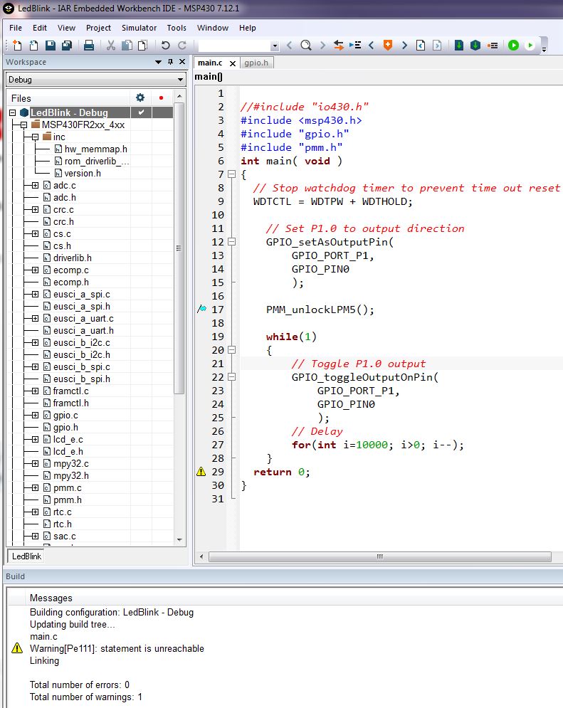
In addition, I used the blink led example provided on the Ti homepage. And tool is iar7.2for msp430.
The IAR tool looks like board is debugging.(Attach picture)

What am I doing wrong? What should i do to use 3.3V?

  • Hello Haeun,

    Thank you for posting, I will look into this issue for you.

    I'm not sure I entirely understand what you are asking, are you saying you want to use 3.3V to power the LED but instead you're getting 5V?

    All the best,

    Colin Adema

  • I want to use 3.3v.  Because I think MCU needs 3.3v.

    And I think...

    The reason you are confused is

    I asked how to turn on the LEDs in the title. But, I said I checked the yellow led in the main text.

    So to summarize,

    Yellow LED checked is on the debug probe.(user guide’s designation: LED102)

    I want to turn on another red led with MCU. (user guide’s designation: LED1)

  • Hello,

    Yes, the MCU uses 3.3V, and consequently you should see 3.3V on LED1. If you're not seeing LED1 turn on, then include the following line of code after line 63:

    PM5CTL0 &= ~LOCKLPM5;

    What that line of code does is disable the GPIO power-on default high-impedance mode. This should allow you to turn the LED on and off.

    All the best,

    Colin Adema

  • I wrote PMM_unlockLPM5(); at line 71.

    But, 3.3v is not output. and no blink LED1.

    This code was provided by TI.

  • Hello,

    What header on the board are you trying to measure 3.3V from? Are you getting 0V there? 

    Also, double check that the header bridging J10 is present when trying to blink LED1.

    Do you have any extra MSP430FR2433 launchpads to test the code with?

    All the best,

    Colin Adema

  • Hello,

    I measured all 3.3 of the board with an oscilloscope. (J101, J1, J5)

    Only very small voltages were measured on the pins.

    and 5v is measured properly, so also 0v is correct.

    I connected the J10 and experimented.

    I have only one MSP430FR2433 launchpad.

    When the LED1 was connected to 5v, LED1 is on.

    So I do not know why the LED not blink.I connected the usb to the board and debugged it with the provided code.

  • Hello,

    How small of voltages are you getting on the 3.3V pins? It's possible that there is a problem on the launchpad itself where it can't supply the 3.3V.

    Do you have a similar launchpad you could run the same or similar code on?

    All the best,

    Colin Adema

  • Hello,

    Voltage is smaller than 1v.  maybe, 0.5v?

    “It's possible that there is a problem on the launchpad itself where it can't supply the 3.3V.”

    Does it mean there is problem with my board?

    Yes. I have my own adhesion board using msp430fr2433.

    HAEUN

  • Hello,

    Yes, It's possible there's something wrong with the launchpad. I've run several tests with my own MSP-EXP430FR2433 launchpad including running the same code. I've also tested by removing the 3.3V jumper on J101 to see what I would still get on the 3.3V pins via stepping down the 5V on the launchpad, and I measured close to 2.5V.

    If you can, run the same code on the second MSP430FR2433 or a similar launchpad and see if you can get 3.3V.

    All the best,

    Colin Adema

  • If you bridged the 5 V to the input of the MCU, you could have damaged the pin. Did you disconnect the LED before you tested it with 5 V?

  • Hello,

    How has the issue been? Has it been resolved?

    All the best,

    Colin Adema

  • No, I did not solve it.

    Now, I checked flowing 2.8V at 3.3V Pin.

    But, LED1 is no blink and 3.3V flows at P3.1, P1.5.

    Below picture is my project.

    I don't know the solution. 

  • Hello,

    So you're getting 3.3V on some of the GPIO pins but not all of them?

    Did you try running the code on the other MSP430FR2433 board you mentioned?

    All the best,

    Colin Adema

  • Yes. I tryed running the code.

    But, LED1 did not blink.

    So, I give up...

  • Hello,

    I can offer more help to help you resolve the issue. If you're having power issues, it's very possible that your launchpad is broken in some way. I would recommend seeing if you can get another launchpad of the same chip or in the same family of chips

    All the best,

    Colin Adema

**Attention** This is a public forum