Part Number: MSP430FR6047
Hello,
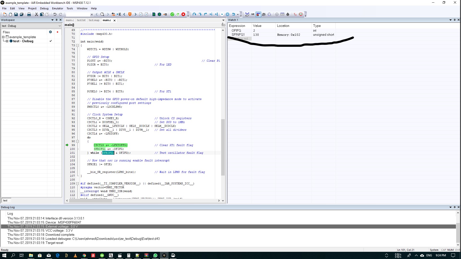
I'm working on MSP430FR6047. I have a problem with the LFXT I connected a 32 kHz crystal oscillator with proper load caps. then loaded the example "msp430fr60x7_cs_05.c" and measured the frequency the output is around 37.5 kHz, not 32.768 kHz. I have changed the crystal and the caps. so I'm certain that the circuitry is good. plus I have tried different driver strength with no hope. I can see that OFIFG is always set and the code is traped in the do-while loop and the OFIFG can't be cleared.
I think this is the fail-safe clock which is 5MHz / 128.
so anyone has an idea.
Ahmed Mohsen
/* --COPYRIGHT--,BSD_EX
 * Copyright (c) 2015, Texas Instruments Incorporated
 * All rights reserved.
 *
 * Redistribution and use in source and binary forms, with or without
 * modification, are permitted provided that the following conditions
 * are met:
 *
 * *  Redistributions of source code must retain the above copyright
 *    notice, this list of conditions and the following disclaimer.
 *
 * *  Redistributions in binary form must reproduce the above copyright
 *    notice, this list of conditions and the following disclaimer in the
 *    documentation and/or other materials provided with the distribution.
 *
 * *  Neither the name of Texas Instruments Incorporated nor the names of
 *    its contributors may be used to endorse or promote products derived
 *    from this software without specific prior written permission.
 *
 * THIS SOFTWARE IS PROVIDED BY THE COPYRIGHT HOLDERS AND CONTRIBUTORS "AS IS"
 * AND ANY EXPRESS OR IMPLIED WARRANTIES, INCLUDING, BUT NOT LIMITED TO,
 * THE IMPLIED WARRANTIES OF MERCHANTABILITY AND FITNESS FOR A PARTICULAR
 * PURPOSE ARE DISCLAIMED. IN NO EVENT SHALL THE COPYRIGHT OWNER OR
 * CONTRIBUTORS BE LIABLE FOR ANY DIRECT, INDIRECT, INCIDENTAL, SPECIAL,
 * EXEMPLARY, OR CONSEQUENTIAL DAMAGES (INCLUDING, BUT NOT LIMITED TO,
 * PROCUREMENT OF SUBSTITUTE GOODS OR SERVICES; LOSS OF USE, DATA, OR PROFITS;
 * OR BUSINESS INTERRUPTION) HOWEVER CAUSED AND ON ANY THEORY OF LIABILITY,
 * WHETHER IN CONTRACT, STRICT LIABILITY, OR TORT (INCLUDING NEGLIGENCE OR
 * OTHERWISE) ARISING IN ANY WAY OUT OF THE USE OF THIS SOFTWARE,
 * EVEN IF ADVISED OF THE POSSIBILITY OF SUCH DAMAGE.
 *
 *******************************************************************************
 *
 *                       MSP430 CODE EXAMPLE DISCLAIMER
 *
 * MSP430 code examples are self-contained low-level programs that typically
 * demonstrate a single peripheral function or device feature in a highly
 * concise manner. For this the code may rely on the device's power-on default
 * register values and settings such as the clock configuration and care must
 * be taken when combining code from several examples to avoid potential side
 * effects. Also see www.ti.com/grace for a GUI- and www.ti.com/msp430ware
 * for an API functional library-approach to peripheral configuration.
 *
 * --/COPYRIGHT--*/
//******************************************************************************
//   MSP430FR60xx Demo - Using LFXT in bypass mode, failsafe operation shown
//
//   Description: ACLK is sourced from LFXT configured in bypass mode.
//   An external 32768 Hz digital input signal is required for this example.
//   When the signal is removed, ACLK defaults to LFMODOSC = 5MHz/128
//   The LED blinks as long as the fault condition remains.
//   Once the fault is fixed, LED goes OFF and ACLK is restored back to the
//   digital input.
//
//   ACLK = External digital in 32kHz, MCLK = SMCLK = 1MHz
//
//           MSP430FR6047
//         ---------------
//     /|\|               |
//      | |               |
//      --|RST            |
//        |               |
//        |      PJ.4/XIN |<-- External 32768Hz required!
//        |          P7.0 |--->ACLK
//        |          P1.0 |--->LED
//
//   Cameron P LaFollette
//   Texas Instruments Inc.
//   November 2017
//   Built with IAR Embedded Workbench V7.10 & Code Composer Studio V7.2
//******************************************************************************
#include <msp430.h>

int main(void)
{
    WDTCTL = WDTPW | WDTHOLD;

    // Configure GPIO
    P1OUT = 0;
    P1DIR |= BIT0;                          // LED setup

    P7DIR |= BIT0;
    P7SEL0 &= ~BIT0;                         // Output ACLK
    P7SEL1 |= BIT0;

    PJSEL0 |= BIT4;

    // Disable the GPIO power-on default high-impedance mode to activate
    // previously configured port settings
    PM5CTL0 &= ~LOCKLPM5;

    // XT1 Setup
    CSCTL0_H = CSKEY_H;                     // Unlock CS registers
    CSCTL1 = DCOFSEL_0;                     // Set DCO to 1MHz
    CSCTL2 = SELA__LFXTCLK | SELS__DCOCLK | SELM__DCOCLK;
    CSCTL3 = DIVA__1 | DIVS__1 | DIVM__1;   // Set all dividers
    CSCTL4 = LFXTBYPASS | HFXTOFF | LFXTOFF;

    do
    {
        CSCTL5 &= ~LFXTOFFG;                // Clear XT1 fault flag
        SFRIFG1 &= ~OFIFG;
    } while (SFRIFG1 & OFIFG);              // Test oscillator fault flag

    // Now that osc is running enable fault interrupt
    SFRIE1 |= OFIE;

    __bis_SR_register(LPM0_bits | GIE);     // Wait in LPM0 for fault flag
    __no_operation();
}

#if defined(__TI_COMPILER_VERSION__) || defined(__IAR_SYSTEMS_ICC__)
#pragma vector=UNMI_VECTOR
__interrupt void UNMI_ISR(void)
#elif defined(__GNUC__)
void __attribute__ ((interrupt(UNMI_VECTOR))) UNMI_ISR (void)
#else
#error Compiler not supported!
#endif
{
    do
    {
        // set a breakpoint on the line below to observe XT1 operating from LFMODOSC
        // when the breakpoint is hit during a crystal fault
        CSCTL5 &= ~LFXTOFFG;                // Clear XT1 fault flag
        SFRIFG1 &= ~OFIFG;
        P1OUT ^= BIT0;
        __delay_cycles(25000);              // time for flag to get set again
    } while (SFRIFG1 & OFIFG);              // Test oscillator fault flag

    P1OUT &= ~BIT0;
}