This thread has been locked.

If you have a related question, please click the "Ask a related question" button in the top right corner. The newly created question will be automatically linked to this question.

MSP430FR6989: Default SMCLK frequency

Part Number: MSP430FR6989

Is the default frequency of the SMCLK 1.048MHz as seen here http://e2e.ti.com/support/microcontrollers/msp430/f/166/t/157922?What-is-MSP430F5XXX-SMCLK-default-frequency-at-Power-on-

or is it automatically calibrated to 1.000 MHz by default? 

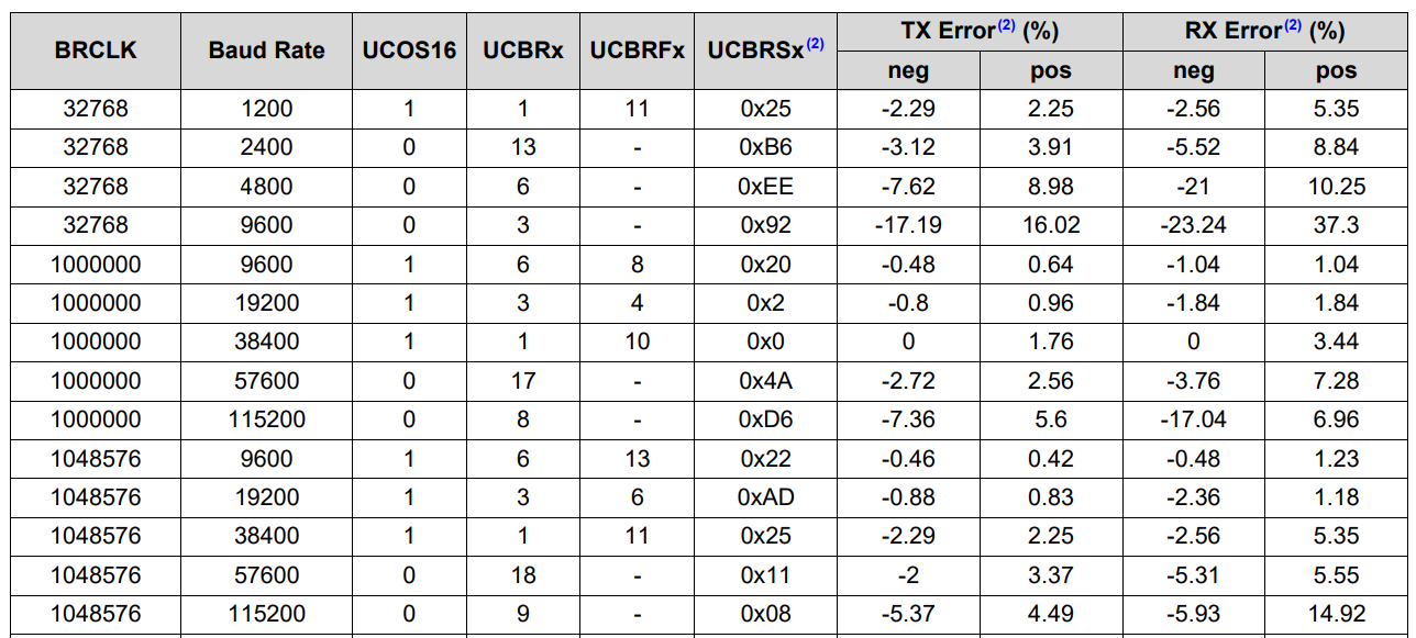
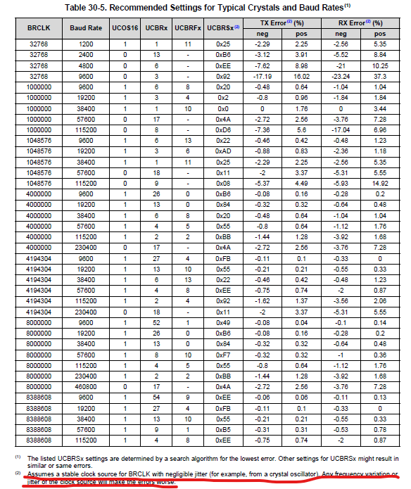
My goal is to choose the correct UCBRx UCBRFx and UCBRSx for UART transmission. I am not sure if the BRCLK would be 1048576 or 100000 by default.

  • Hi Tyler,

    I must to tell you that the clock will not be 1048576 or 100000 actually, because every clock has a jitter . Please see the datasheet.  Normally, we will treat it as 1MHz, the jitter is not taken into consideration. Please see the second chart. You can just set the registers according to the chart.

    Eason

  • Thank you that makes sense as it is sourced by RC which has a larger error tolerance. I have one follow up question:

    You said "Normally, we will treat it as 1MHz"

    is 1MHz considered to be 1000000 or 1048576? 

  • Hi,

    1MHz is considered to be 1000000. You can also check by yourself. Here is the test code. You can output SMCLK from GPIO.

    Eason

    msp430fr69xx_cs_03.c
    /* --COPYRIGHT--,BSD_EX
     * Copyright (c) 2014, Texas Instruments Incorporated
     * All rights reserved.
     *
     * Redistribution and use in source and binary forms, with or without
     * modification, are permitted provided that the following conditions
     * are met:
     *
     * *  Redistributions of source code must retain the above copyright
     *    notice, this list of conditions and the following disclaimer.
     *
     * *  Redistributions in binary form must reproduce the above copyright
     *    notice, this list of conditions and the following disclaimer in the
     *    documentation and/or other materials provided with the distribution.
     *
     * *  Neither the name of Texas Instruments Incorporated nor the names of
     *    its contributors may be used to endorse or promote products derived
     *    from this software without specific prior written permission.
     *
     * THIS SOFTWARE IS PROVIDED BY THE COPYRIGHT HOLDERS AND CONTRIBUTORS "AS IS"
     * AND ANY EXPRESS OR IMPLIED WARRANTIES, INCLUDING, BUT NOT LIMITED TO,
     * THE IMPLIED WARRANTIES OF MERCHANTABILITY AND FITNESS FOR A PARTICULAR
     * PURPOSE ARE DISCLAIMED. IN NO EVENT SHALL THE COPYRIGHT OWNER OR
     * CONTRIBUTORS BE LIABLE FOR ANY DIRECT, INDIRECT, INCIDENTAL, SPECIAL,
     * EXEMPLARY, OR CONSEQUENTIAL DAMAGES (INCLUDING, BUT NOT LIMITED TO,
     * PROCUREMENT OF SUBSTITUTE GOODS OR SERVICES; LOSS OF USE, DATA, OR PROFITS;
     * OR BUSINESS INTERRUPTION) HOWEVER CAUSED AND ON ANY THEORY OF LIABILITY,
     * WHETHER IN CONTRACT, STRICT LIABILITY, OR TORT (INCLUDING NEGLIGENCE OR
     * OTHERWISE) ARISING IN ANY WAY OUT OF THE USE OF THIS SOFTWARE,
     * EVEN IF ADVISED OF THE POSSIBILITY OF SUCH DAMAGE.
     *
     *******************************************************************************
     * 
     *                       MSP430 CODE EXAMPLE DISCLAIMER
     *
     * MSP430 code examples are self-contained low-level programs that typically
     * demonstrate a single peripheral function or device feature in a highly
     * concise manner. For this the code may rely on the device's power-on default
     * register values and settings such as the clock configuration and care must
     * be taken when combining code from several examples to avoid potential side
     * effects. Also see www.ti.com/grace for a GUI- and www.ti.com/msp430ware
     * for an API functional library-approach to peripheral configuration.
     *
     * --/COPYRIGHT--*/
    //******************************************************************************
    //   MSP430FR69xx Demo - Output 32768Hz crystal on XT1 and observe failsafe
    //
    //   Description: Configure ACLK = LFXT1 and enter LPM3.
    //   To observe failsafe behavior short the crystal briefly on the target board.
    //   This will cause an NMI to occur. P1.0 is toggled inside the NMI ISR.
    //   Once the fault flag is cleared XT1 operation continues from 32768Hz crystal
    //   Otherwise ACLK defaults to LFMODCLK (~37.5KHz).
    //   ACLK = LFXT1 = 32kHz, MCLK = SMCLK = 1MHz
    //
    //           MSP430FR6989
    //         ---------------
    //     /|\|            XIN|-
    //      | |               | 32KHz Crystal
    //      --|RST        XOUT|-
    //        |               |
    //        |           P5.2|---> ACLK = 32.768kHz (or 37.5kHz during LFXTOFFG)
    //        |           P7.4|---> SMCLK = MCLK = 1MHz
    //        |           P1.0|---> LED
    //
    //   William Goh
    //   Texas Instruments Inc.
    //   April 2014
    //   Built with IAR Embedded Workbench V5.60 & Code Composer Studio V6.0
    //******************************************************************************
    #include <msp430.h>
    
    int main(void)
    {
      WDTCTL = WDTPW | WDTHOLD;
    
      // GPIO Setup
      P1OUT = 0;
      P1DIR = BIT0;                             // For LED
    
      P5DIR |= BIT2;
      P5SEL0 |= BIT2;                           // Output ACLK
      P5SEL1 |= BIT2;
    
      P7DIR |= BIT4;
      P7SEL0 |= BIT4;
      P7SEL1 |= BIT4;                           // Output SMCLK
    
      PJSEL0 = BIT4 | BIT5;                     // For XT1
    
      // Disable the GPIO power-on default high-impedance mode to activate
      // previously configured port settings
      PM5CTL0 &= ~LOCKLPM5;
    
      // Clock System Setup
      CSCTL0_H = CSKEY >> 8;                    // Unlock CS registers
      CSCTL1 = DCOFSEL_0;                       // Set DCO to 1MHz
      CSCTL2 = SELA__LFXTCLK | SELS__DCOCLK | SELM__DCOCLK;
      CSCTL3 = DIVA__1 | DIVS__1 | DIVM__1;     // Set all dividers
      CSCTL4 &= ~LFXTOFF;
      do
      {
        CSCTL5 &= ~LFXTOFFG;                    // Clear XT1 fault flag
        SFRIFG1 &= ~OFIFG;
      }while (SFRIFG1&OFIFG);                   // Test oscillator fault flag
    
      // Now that osc is running enable fault interrupt
      SFRIE1 |= OFIE;
    
      __bis_SR_register(LPM0_bits);             // Wait in LPM0 for fault flag
    }
    
    #if defined(__TI_COMPILER_VERSION__) || defined(__IAR_SYSTEMS_ICC__)
    #pragma vector=UNMI_VECTOR
    __interrupt void UNMI_ISR(void)
    #elif defined(__GNUC__)
    void __attribute__ ((interrupt(UNMI_VECTOR))) UNMI_ISR (void)
    #else
    #error Compiler not supported!
    #endif
    {
      do
      {
        // set a breakpoint on the line below to observe XT1 operating from VLO
        // when the breakpoint is hit during a crystal fault
        CSCTL5 &= ~LFXTOFFG;                    // Clear XT1 fault flag
        SFRIFG1 &= ~OFIFG;
        P1OUT |= BIT0;
        __delay_cycles(25000);                  // time for flag to get set again
      }while (SFRIFG1&OFIFG);                   // Test oscillator fault flag
    
      P1OUT &= ~BIT0;
    }
    

**Attention** This is a public forum