This thread has been locked.
If you have a related question, please click the "Ask a related question" button in the top right corner. The newly created question will be automatically linked to this question.
Tool/software: Code Composer Studio
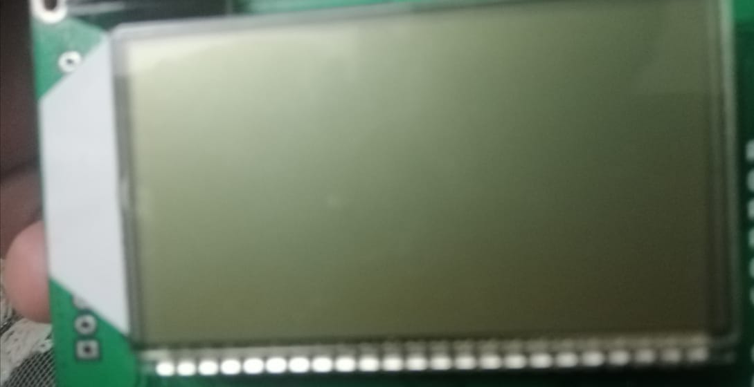
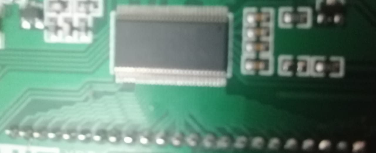
I have MSP430FR4133(56 pin) controller and there is LCD connected with it's pin from 35 to 56 pin(LCD pins) but i do not know the lcd pins or where is the data sheer of this LCD and LCD nothing wrote on it.
any help how to write on the LCD.
Hello,
If you don't have the structure of the LCD, I'm afraid that I can't help you.
If you're using the Launchpad, the LCD part number is probably in the BOM, in the Design Files (.zip) available on the product page. Launchpad User Guide (SLAU595A) Table 3 calls it a "FH-1138P".
http://www.ti.com/tool/MSP-EXP430FR4133
That zip file also apparently contains examples specific to the Launchpad, at least some of which presumably use the LCD. The I think there are some wiring conventions for segment LCDs, so you might be able to use pieces of the Examples without a Launchpad.
There are also code examples, including for the LCDE, at:
http://dev.ti.com/tirex/explore/node?node=AL42JTImOOwWpUAlbx0W1w__IOGqZri__LATEST
hi,
i tried the example lcd_01.c and it did not work, the lcd start blanks and didn't show any thing, please help
Is there any marking on the board to indicate a part number. If you look at the IC really close, you might be able to use the part number to get a data sheet.
Example LCDE_01 expects to see a 32kHz crystal, and I don't see one of those on your board. The crystal is not actually required (on the FR4133). The first experiment might be to remove these lines:
#if 0 // Configure XT1 oscillator P4SEL0 |= BIT1 | BIT2; // P4.2~P4.1: crystal pins do { CSCTL7 &= ~(XT1OFFG | DCOFFG); // Clear XT1 and DCO fault flag SFRIFG1 &= ~OFIFG; }while (SFRIFG1 & OFIFG); // Test oscillator fault flag CSCTL6 = (CSCTL6 & ~(XT1DRIVE_3)) | XT1DRIVE_2; // Higher drive strengthr #endif // 0
I looked at the whole board but I didn't find anything all I know that the board connected parallel to LCD pins, any tips to know LCD pins from LCD itself. I can try.
The LCD interface chip is probably a Hitachi HD44780. You can google the datasheet for that and see if the connections make sense.
it also did not work, when come to this line:
LCDCTL0 |= LCD4MUX | LCDON;
LCD start blinking very fast and make sound. any another tips?
unfortunately it is not Hitachi HD44780 i i think this lcd can write on it in arabic words.
Sorry, I missed this:
> LCDCTL0 = LCDSSEL_0 | LCDDIV_7; // flcd ref freq is xtclk
LCDSSEL=0 is XT1CLK (the code you just removed since it didn't work). This should make it use ACLK (REFOCLK, an internal oscillator) instead:
> LCDCTL0 = LCDSSEL_1 | LCDDIV_7; // flcd ref freq is ACLK (REFOCLK)
-----------------
I'm hoping that gets rid of the squeal. If you still don't see anything, the next experiment I was going to suggest was writing 0xFFFF into all the segment memory. I did this on my Launchpad from the debugger (Registers->LCD_E->LCDM0W, LCDM2W, and so on). We don't know what the segment map is, but if we light up enough of them I'm hoping you'll see something.
-----------------
Arabic segments sounds pretty exotic. I hope you'll post a photo when you get there.
it started to show some thing on the lcd and after trying a lot the lcd all appear.
also i made this configuration :
////////////////////////////////////////////////////////////////////////////////////////////////////////////////////////////////////////////////////////////////////////////////////////////////////////////////////////////////////
LCDPCTL0 = 0xFF00;
LCDPCTL1 = 0xFFFF; // L8~L23 pins selected because i used pins from 8 to 23
LCDCSSEL0 = 0x00AA; // Configure COMs and SEGs
LCDCSSEL1 = 0x0000;
////////////////////////////////////////////////////////////////////////////////////////////////////////////////////////////////////////////////////////////////////////////////////////////////////////////////////////////////////
is that right, configuration ?
If this configuration works, that's a good sign.
>LCDCSSEL0 = 0x00AA;
This says that L1/L3/L5/L7 are connected to COM0-3 on the LCD.. (The Launchpad uses L0-L3 for this.) If this is the way it's wired -- you can see the board better than I -- it seems fine.
The example also sets the COMx "segments" =1 in the LCDMEM (LCDM0/1). For this case, and looking at the Launchpad User Guide (SLAU595A) Table 4, I think this would translate to:
> LCDM0 = 0x10; // L1=COM0
> LCDM1 = 0x20; // L3=COM1
> LCDM2 = 0x40; // L5=COM2
> LCDM3 = 0x80; // L7=COM3
But go with what works.
**Attention** This is a public forum