This thread has been locked.

If you have a related question, please click the "Ask a related question" button in the top right corner. The newly created question will be automatically linked to this question.

CCS/MSP430F5529: DRV8350_EVM used the on board ez_lite emulator MSP430f5528 and MCU (MSP430F5529),but can not work.

Part Number: MSP430F5529
Other Parts Discussed in Thread: DRV8350, , MSP430F5528, UNIFLASH, LM5008A

Tool/software: Code Composer Studio

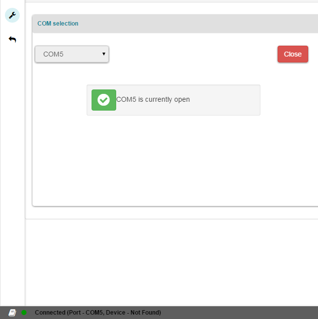
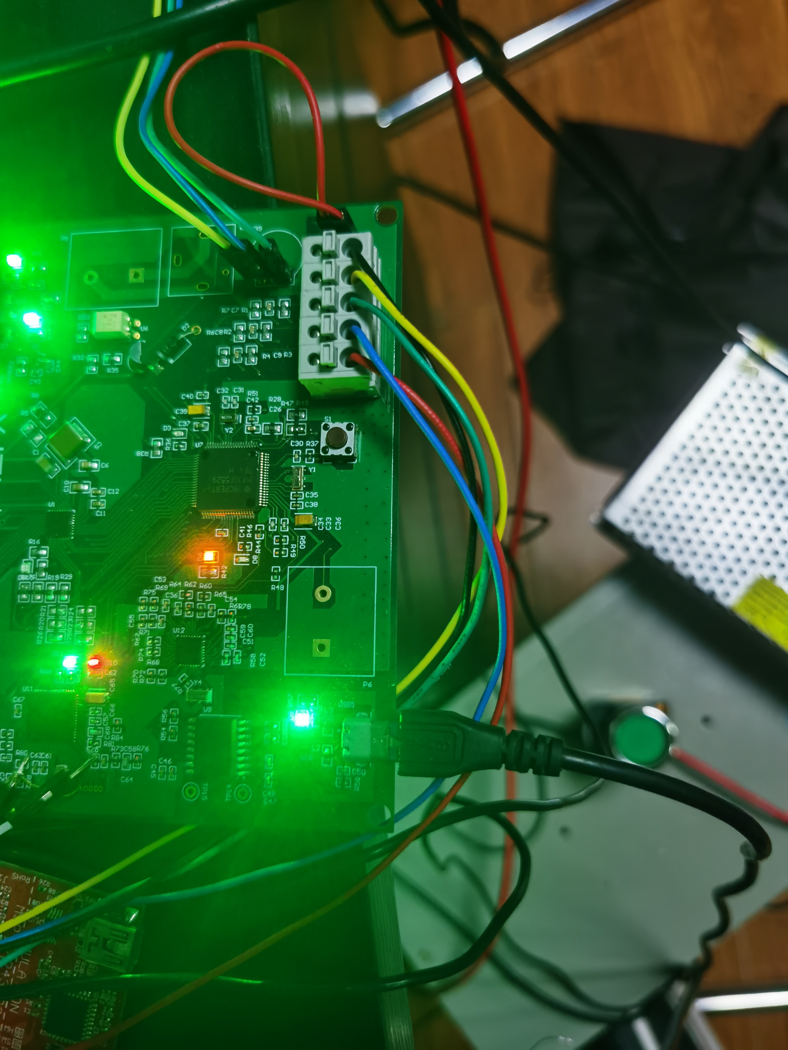
I have referenced the DRV8350_EVM and developed my own board.With the help of Ti experts from the following threadhttps://e2e.ti.com/support/motor-drivers/f/38/p/904538/3359289#3359289,I have achieved the communication with PC, but there is still a problem in front of me . as the DRV8350_EVM user guide shows when I installed the file of Setup_DRV8350x-1.0.0_EVM.exe, The COM port TI MSP430 USB will installed.

But it failed .So I followed the file of Examples_Guide_MSP430_USB.pdf and run the CDC example towards the CCS. it still didn't work.

It can load the CDC example during debug. Just like below.


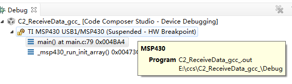
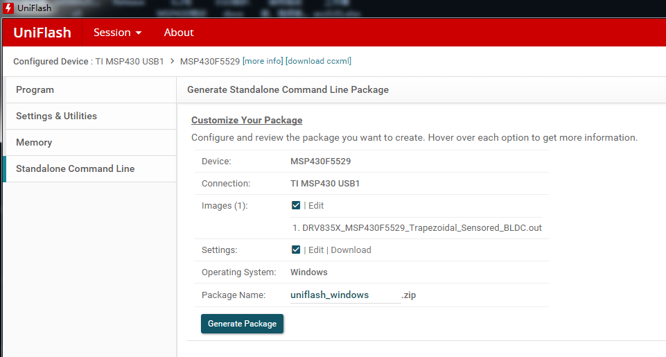
It all looks well.But when I debug the example in the folder of E:\ccs\DRV8350x_EVM_BLDC_FW_1.0.0\DRV835X_MSP430F5529_Trapezoidal_Sensored_BLDC(It is decompressed  from Ti source file).

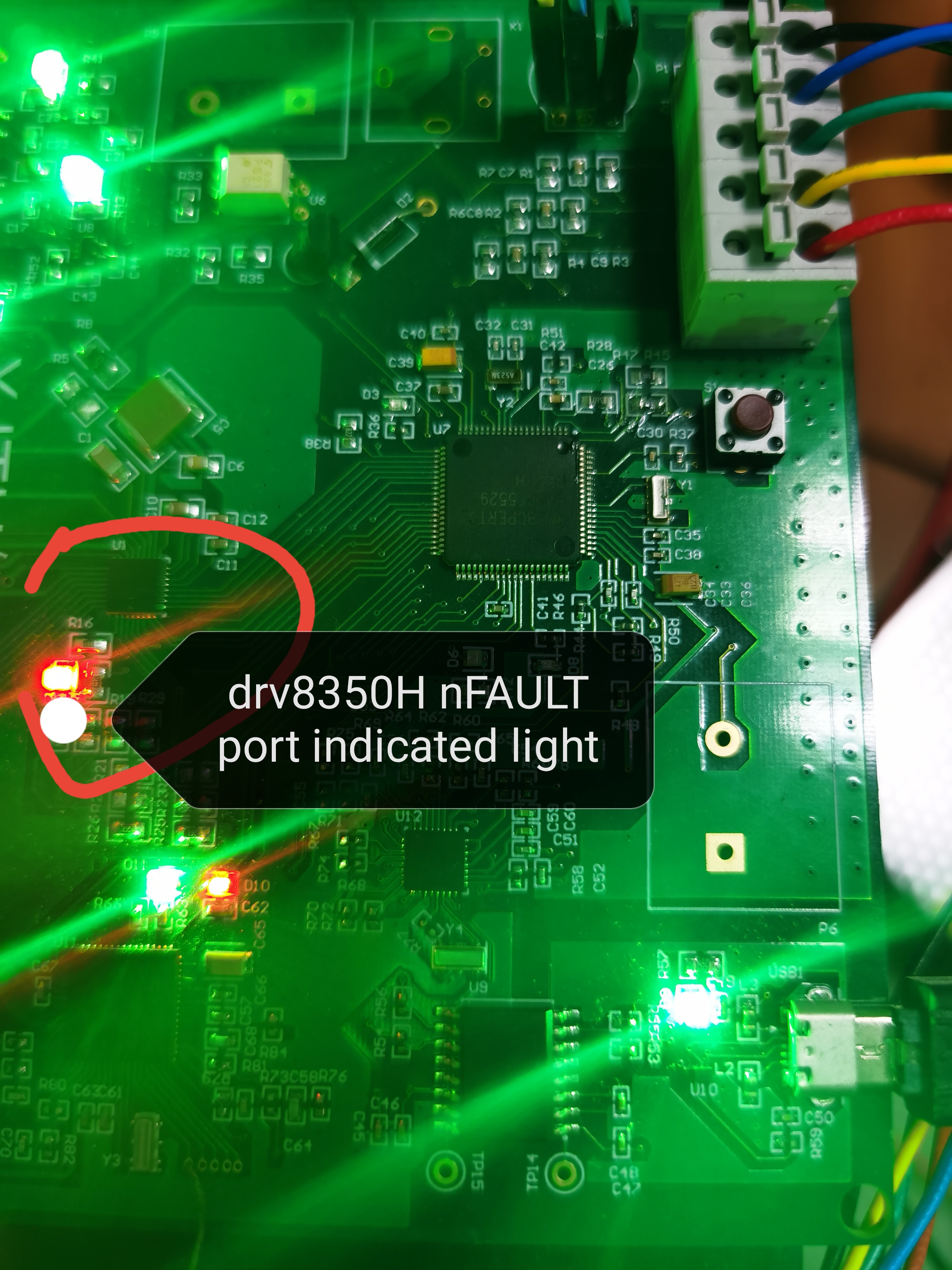
It has a fault of disconnect like below. What's wrong?

  • Hello,

    That seems strange that you get this disconnected status since the UART and debug interface COM ports seem to be enumerated correctly.  What version of CCS are you using?  If not the latest, you should try updating to see if the problem persists.  

    http://www.ti.com/tool/CCSTUDIO

  • I have tried the lastest version of CCS, It still shows the disconnected status.But this time I can communicate it with my PC when I debug the program of DRV835X_MSP430F5529_Trapezoidal_Sensored_BLDC, when  I downloaded the program to the MSP430F5529, The motor didn't work. I am still debuging .So I want to ask if there are debug uerguide about the program of DRV835X_MSP430F5529_Trapezoidal_Sensored_BLDC.

  • The users guides can be found below.

    1. General EVM User's Guide: http://www.ti.com/lit/ug/slvub78a/slvub78a.pdf
    2. Specific Sensored Firmware User's Guide: http://www.ti.com/lit/ug/slvub82/slvub82.pdf
    3. Specific Sensorless Firmware User's Guide: http://www.ti.com/lit/ug/slvub81/slvub81.pdf
  • Thank you for your reply.

    I wish you all the best.

    Because there is no COM Port of TI MSP430 USB ,   so I can not use the  DRV8350X EVM GUI

    It's so strange that when I use the CCS and download the program to the board,the default connection is TI MSP430 USB1, it works.

    but it doesn't show in the device manager.what's wrong ? How can I have the COM port and use the DRV8350X EVM GUI?

  • When I load the program to the target board of MSP430F5529,It didn't works. sometimes the red led indicates MCU FAULT. what's this can illustrate?

    Why I followed the file of Examples_Guide_MSP430_USB.pdf,but it still have no COM of MSP430 USB when I powered my board and connect it to PC.

  • Hello,

    So you are able to load the code to MSP430, but no COM port is shown in device manager?  In your original post, it looks like it is showing the MSP Application UART on COM 5.  When connecting to the EVM in the GUI, are you able to manually select this port?

    Can you also provide your schematic?

  • Hello Eddie,

    Thank you so much for your reply. yes it shows the MSP Application UART on COM5, but when I sellected the COM5 in the EVM GUI, it showed CONNECTED BUT NO DEVICE FOUND,Just like below.

    Here is the schematic. I just added some other feature. But I didn't modify the main function of the schematic.

    New_drv8350_evm.rar

  • Hello,

    Thanks for the schematic.  The schematic includes one MSP430F5528 used for the eZ-FET and MSP430F5529 used for the application.  I want to be sure that you have the correct firmware in the MSP430F5528.  This can be found below.  It does not look like you have the programming pins(JTAG or SBW) brought out from the schematic though.  Have you programmed this MSP430F5528? 

    http://software-dl.ti.com/msp430/msp430_public_sw/mcu/msp430/MSP430_ezFETLite/latest/index_FDS.html

  • Hello,

    Yes. Of course I have properly programmed the5528.just like the picture below. Now I can download the firmware to the MSP430F5529, the problem I'm facing is two aspect.

    1.i I can not drv8350x_evm GUI. When I connect the board, it didn't show the COM Port of MSP 430 USB. But I have tried the instructions from you, when I selected the Uart port, it showed no device found just like the above thread.

    2. When I download the program to 5529, it didn't work. I have also followed the instructions and modified the parameters in the program of drv8350_evm. It seems do not work too.

    Can you give me further instruction?

    Looking forward to your reply.

  • Ok.  Thanks for confirming. 

    1. Since it is showing the COM port in device manager, but not the GUI application, it is possibly a baud rate problem.  In the device manager, is the baud rate set to 9600?  It looks like the code is setting UART for 9600 baud.  Also, see if you can get an oscilloscope on the UART lines to see if there is any communication happening. 

    2. If the code is building in CCS and runs, it may be a problem with the version of CCS you are building with.  The users guide mentioned it has been tested with version 5 and 6.  It should build properly with a newer version of CCS, but sometimes there are problems.  To see if it is some problem when building with a newer version of CCS, you could try loading the pre built .out file that is available when you download the code package.  The .out file can be found in the directory below if you installed in the default directory.  You can use uniflash to load the .out file(https://www.ti.com/tool/UNIFLASH). 

    C:\ti\DRV8350x_EVM_BLDC_FW_1.0.0\DRV8350x_EVM_FW\DRV8350x_EVM_BLDC_FW_1.0.0\DRV835X_MSP430F5529_Trapezoidal_Sensored_BLDC\Debug

  • Dear Eddie,

    Thanks for your reply.

    1.I have confirmed that the baud rate is 9600 in the device manager.  It's so strange that when I use the Uniflash to download the firmware to MSP430F5529 from the code package , It can show the connection is TI MSP430 USB1, but when I use the DRV8350_EVM GUI, It doesn't show this connection.like the picture below.

    2.As I have download the old .out file to the 430F5529 from the code package, It also didn't work.like below,I can download the firmware successfully. But as the LED showing I am using the IDE and the firmware is also running in the MSP430F5529, but I can not spin the motor.I used the CCS Debug tools , but find out nothing . so how can I further my research and find out the bug in my design. This really confused me so long.


  • Last thing to try is see if the USB example below work with your hardware.  If this works properly, I will need to move this thread to the DRV team.

    http://software-dl.ti.com/msp430/msp430_public_sw/mcu/msp430/MSP430_USB_Developers_Package/latest/index_FDS.html

  • Hello Eddie,

    I have tried the USB example below the path D:\MSP430USBDevelopersPackage_5_20_06_02\MSP430USBDevelopersPackage_5_20_06_02\MSP430_USB_Software\MSP430_USB_API\examples\CDC_virtualCOMport\C0_SimpleSend

    But as I run the code ,the LED light which indicate the drv8350H nFAUNT port  has on.what can this illustrate?ike the picture below.I have read the code of example which is named C0_SimpleSend , It init the all GPIO low first, so the nFAUNT port in the MSP430F5529 is low, but can this affect the level of the output level in the port of NFAUNT in the drv8350?


  • Hello Eddie,

    Just now ,I tried a new board and followed the instruction to have finished programming MSP430F5528, Now it installed the all COM Port, just like below.

    So I can use the GUI of Drv8350x EVM. But as I enabled the DRV8350H device, the NFault indicated led light on, it shows unknow error,  So how can I further my debug.

    Could you please help me to put this thread to the TI MSP430 DRV team?

  • Scalery,

    Please check and let us know the following near the DRV while the fault LED is lit:

    VM, VDRAIN, VCP, VGLS voltages?

    Are you switching the outputs when the nFAULT LED is lit?

    Regards,

    -Adam

  • 1.When the board is lited, VM=5.4v,it's  so strange that I used the LM5008A to transfer 24v to 12v, It worked well before and  can output 12V,  Now it became 5.4v,and I have test the pin FB of Lm5008A , commonly it is 2.5V, now it became 1.1V......

    2.VDRAIN=24.2V

    3.Vcp=24.2v

    4.VGLS=0V,

    all above is not tested when the fault Led lit.

    only when I enable the DRV, the LED will lit. 

  • Scalery,

    You are having VM Undervoltage which is causing the fault. Can you supply ~10V to VM with some external supply and check if the fault issue goes away?

    Regards,

    -Adam

  • Yes, as following your suggestion, there is no fault LED lit, but it remind HALL CALIBRATION FAULT?

  • Scalery,

    Have you confirmed that the hall signals are switching when the motor turns as seen at the pins of the DRV?

    Please show us the error.

    Regards,

    -Adam

  • I have tried just now, as the motor turns the hall signals didn't switch and always 3.4v,but as I supply the  supply 5v to HALL sensor independently, and turn the motor spin , I test the HALL output pin ,the signal are switching. so It's not the problem of motor. as I use the GUI ,It indicate the below error.

  • Scalery,

    Did you try the Auto Hall calibration?

    Regards,

    -Adam

  • yes,as I used the AUTO HALL CALIBRATION it showed the same fault of HALL CALIBRATION, and I  tried to forward the direction of motor , It indicated invalid HALL sensor?  

    I can see the motor spined a angle to calibrate the HALL, But why it still indicated the HALL CALIBRATION fault?like below.

    And I have tried to debug the program in ccs ,It also jump in the loop which indicated that CalibrationHall not true.It always run in the SYSTEM_IDLE and then BREAK. just like below.

  • Dear Adam,

    seemingly, I have find out the reason why it indicated Hall Calibration Fault,

    From the DRV8350X _EVM user guide, it indicated if using sensored firmware, It should solder the unpopulated R82 ,R84 and  R86 0ohm resisitor.like below.

    But I found there are no these 0 ohm resisitors in the design schematic of drv8350_evm.

    so I need to confirm if it is Hall sensor 0ohm resistor R46, R48, R51.


  • Scalery,

    The EVM is intended for 6X PWM mode by default and you can add those 0 ohm resistors if you want to change it to 1X PWM.

    Regards,

    -Adam

  • Thank you Adam,

    Fine, I know about that, I just want to know where is the R82,R84 and R86 resisitor in the schematic of EVM.

    additionnally , How to debug the HALL CALIBRATION problem?

  • Scalery,

    My schematic does not have R84 or R86, I am not sure what you are referencing.

    I don't know how to solve your calibration issue.

    We do not recommend reproducing the EVM as your own board because it creates issues like this where the board is partially your design and partially our design.

    Regards,

    -Adam

  • Hello Adam,

    The resisitor R82, R84 and R86 are In the schematic of DRV8350x-EVM user's guide.

    As the firmware is running in the MSP430F5529, I have meassured the signal of HALL receiver in the board ,It didn't switching as I turned the motor spin.so I think if the MCU do not work well...

    Best Regards,

    Scalery

  • Scalery,

    The resistors for modifying the EVM to connect the hall sensors to the DRV are R46, R48, and R51 in the schematic. The mentions of R82/R84/R86 are incorrect in the User's guide and I will correct this.

    Regards,

    -Adam

  • So it means if I use the sensored firmware. I need to solder the R46 , R48 and R51?

  • Hello Adam,

    sorry to bother you again, this morning I have tried again as I have solder the unpopulated resistor.

    now it can CALIBRATE HALL, but it indicated HALL SENSOR INVALID. I have also test the signal in the board of hall sensor reciever. It is 0.28v ,0.12v and 0.28V,

    below is the picture from   the oscilloscope.I have checked the firmware and it is right configured the IO port. and also I have supplied the 5v to HALL SENSOR independently and measured the output signal. it is 110 100,101 001 011 010 .it is switching.why when I connected the HALL SENSOR to the board ,It did not switch. How to check if it is hardware problem or software problem?

  • Scalery,

    Please show me the complete schematic of your hall sensors and a picture of the hardware connections on the board.

    Regards,

    -Adam

  • Hello Adam,

    Thank you for your reply.The file below is schematic which contains the complete HALL SENSOR  connection. and picture shows the HALL SENSOR schematic.

    Gate_driver.pdf

    The picture below is the hardware connection of HALL SENSOR.

     Looking forward to your reply.

    Scalery.

  • Scalery,

    Can you share your motor datasheet?

    Also can you probe INLA/INHB/INLB with with board and motor fully powered?

    Please spin the motor by hand and show us the 6 different hall states on the scope in the powered condition.

    Regards,

    -Adam

  • Hello Adam,

    Thank you so much for your reply.

    The file below is my motor datasheet.

    57BLY110-220-A08-Model.pdf

    Also I have tested the INLA/INLB/INHB with motor and board fully powered. bacause I have not designed the test point in my board.so I just used the multimeter and test the INLA/INLB/INHB ,It all indicated 0.11V,but as the motor tried running , the number is changing but eventually it stand in 0.11V.

    Below is the 6 different hall state on the scope ,but bacause the scope only have two channels  so I only test two channels.below is the video.

  • Scalery,

    The DMM cannot be used to measure the hall output as it will give the average of the hall signal AC waveform and is often not fast enough to respond to the real hall output signal.

    Since you have a two channel scope, could you probe HALLA output and HALLB output at the same time? Then check HALLB and HALLC in a second plot.

    I also see that your hall output is sinusoidal, this output should be a square wave. Can you show us with a picture where you are measuring the hall output?

    Can you show us an image of the motor connections to the board?

    Regards,

    -Adam

  • Hello Adam, 

    Thank you for your reply.I hope I can resolve this problem with your help. 

    I know The DMM measures the average output level ,but I need to fly line first in the signal point of INLA/INHB/INLB and then measure the output use scope.I will reply the measured result later.

    The picture below is the whole connection of my board , motor and measuring point of HALL signal  using the scope.

     Just followed your instruction ,below is the HALLA/HALLB output and HALLA/ HALLC output. yesterday I independently measured the HALL output without connecting to the board but only supplied 5V power to the motor and spined the motor .today I measured the HALL output with  my board fully powerd  .

    I have looked the ouput ,It's really terrible. and output level is different.

  • Hi Adam,

    I'm waiting for the answer. can you afford me some advise about this kind of problem. I find HALL SENSOR output is really terrible, So if it is useful to create shaping circuit to make HALL SENSOR output more squared? or it is my hardware problem?

  • Scalery,

    I am not sure why your hall sensor is having this issue. I would contact your motor manufacturer.

    Regards,

    -Adam

  • Hello Adam,

    Thank you so much , if it is not convenient for you , you can post all the questions for me , I can contact the motor manufacturer.

    Regards ,

    Scalery

**Attention** This is a public forum