Because of the holidays, TI E2E™ design support forum responses will be delayed from Dec. 25 through Jan. 2. Thank you for your patience.

This thread has been locked.

If you have a related question, please click the "Ask a related question" button in the top right corner. The newly created question will be automatically linked to this question.

CCS/MSP432P401R: BPSK Modulation and Demodulation Sample Code Not Working

Part Number: MSP432P401R

Tool/software: Code Composer Studio

Hello,

I have been attempting to use the BPSK modulation and demodulation code to setup a simple transmit/receive system. The code was acquired through this forum:

https://e2e.ti.com/support/microcontrollers/msp430/f/166/t/899342

The modulation code produces nothing on the output P2.5. It appears this has been noted in another question but I cannot find the fix. Here is the link to the original inquiry about this issue:

https://e2e.ti.com/support/microcontrollers/msp430/f/166/t/759349

The code is untouched and is successfully compiling and loading to the target MSP432P401R LaunchPad Evaluation Board unlike what the OP had noted. My code, however, runs into the same problem that his eventually ran into, i.e., no signal on the output pin 2.5. Ultimately, I am unable to test the demodulator without a proper modulator. 

Please advise on this issue.

  • Did you push the P1.1 button?

  • Hello Bruce,

    Thank you for that information. I did not see a mention of this button usage within the code so thank you for pointing that out to me. I now understand that the code that dealt with the button and interrupt service routine was in PORT1_IRQHandler. It appears the system is now sending some form of data but I am unsure how it is adhering to a specific frequency as the button can be pushed randomly. 

    Can you provide answers to the following questions, please?

    - I see the bit rate is set to 125kbps, however, upon succession of button presses my oscilloscope registers the frequency of the waveform as 5kHz. Can you explain the reasoning behind this?

    - What variable is the data to be modulated stored in? I assumed sendTestData.

    - What data is being sent with the button press?

    - If the data that is being sent to the demodulator is in fact sendData/sendTestData then the demodulator does not appear to be functioning as a previous forum had pointed out. What is the variable in the demodulator program that contains the demodulated data? I believe it is receivebuffer[] but it contains junk data. 

    Please advise when given the chance.

    Kind Regards,

    Joe

  • I'll admit here that all I know about this is from reading the code enough to answer your original question. I suspect some of these questions are answered by the document.

    What I saw in the burst from the button was what looked like a carrier (P2.4) and an encoded (could be BPSK) square wave (P2.5). My scope said it was 125kHz.

    As I read this, sendData[] is encoded into buffer[]/sendBuffer, then metered out one bit (symbol) at a time.  Based on Packet..c, the packet has the data with (maybe) FEC bits interleaved, some sync bytes, a preamble, and a CRC. 

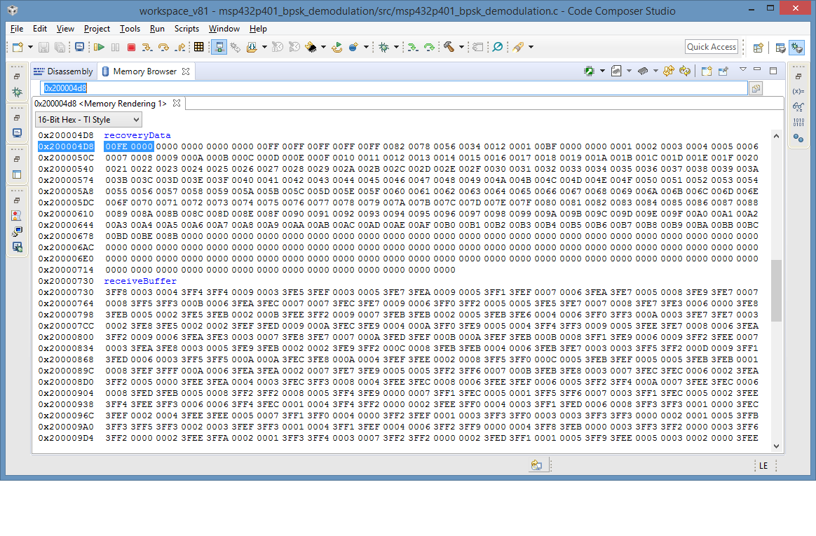
    It looks like the demodulated result is put in recoveryData[].

    How are you testing this? Are you just wiring two Launchpads together?

    If I can find another Launchpad I may try to connect them and see what I get. In the meantime, one experiment might be to slow the data rate.

  • Hello Bruce,

    I do indeed see a frequency of 5.0kHz with my scope on both the data and carrier pins (P2.5 and P2.4, respectively). I am wiring two launchpads together with one functioning as a modulator and one acting as the demodulator. Just to be clear, when you say to slow down the data rate you mean to adjust the bit rate in the modulator file that is currently set to 125kHz? I was thinking that one possible measure is to slow it down to 5.0kHz to see its effects. Currently, recoveryData[] is most certainty not what is being populated inside of sendData[] on the modulation side. 

    Your continued assistance is appreciated!

    Regards,

    Joe

  • I haven't been able to find my spare Launchpad, so for now all I can do is gab. (I did demonstrate that it won't run/build on a P4111, in case anyone's curious.)

    I should also mention that CCS imported the projects, but made a mess of them, so I pretty much re-built them. I made a point not to touch the source, though.

    It seems as though the disagreement between our scopes (125kHz vs 5kHz carrier) should be a clue. There's also the fact that the stack size (in the original) is set to 0.5KB, but main() by itself is using much more than that; I chose not to change it, and it (the modulator at least) runs fine anyway.

    What does recoveryData[] look like?

  • Hello Bruce,

    Please reference the following print screens of recoveryData[]. There does not seem to be a rhyme or reason to the data that is demodulated. Note that the modulated data to be expected was that of the sendData[] variable from the modulation program. I still have the two launchpads connected. Please do note that these launchpads utilize the MSP432P401R. The pinout I have is the following:

    GND on J2 (Modulator Board) connected to GND on J3 (Demodulator Board)

    P2.5 on J2 (Modulator Board) connected to P5.5 on J3 (Demodulator Board)

    This is the hardware setup they show in slaa681a.pdf. This pinout is the .pdf explanation of the given BPSK modulation program. 

    I have attached the images below:

    [See follow-up post for image correction.]

    Please note that the images I have attached are right before the execution of the decoder statement in line 146. After line 146 is continually ran, all of the values appear to be turned into 255. The bit rate that the system is currently set for is 5kHz. I will readjust it to 125kHz and provide more pictures within the closing of today in the manner stated in the following post.

    Again, your continued assistance is appreciated!

    Regards,

    Joseph Blank

    Please note that I have edited this post from its original content.

  • Hello Bruce,

    I attached the images that were supposed to show up in my previous post inside a word document. 

    I will upload images of the data before modulation and after modulation (if it ends up being something different than 255) with the 125kHz baud rate by the end of business today.

    Regards,

    Joseph Blank

    MSP432_Demodulation_recoverydata[].docx

  • Hello Bruce,

    Please find attached another word document that includes results of the demodulation data. This time the baud rate was set to 125kHz. Tomorrow, I will be working with clean versions of the program and rerun to see if the results change. At the moment, the results are showing no data (all zeros). Can you share your projects (for modulation and demodulation) per chance to see if I have set it up properly? I have also attached an image from slaa681.pdf. This .pdf shows the BPSK transmission. Could you confirm if your output looks like that? Mine is a singular square wave pulse at 5kHz. It looks nothing like that.MSP432_Demodulation_recoverydata[]_125kHz.docx

    Your continued assistance is appreciated!

    Regards,

    Joseph Blank

  • My traces looked superficially like Figure 15, in that (by comparing with the carrier) I could see phase reversals scattered through the signal. I don't know where in the sequence Fig 15 was taken from, so there's no reason to suppose it matches exactly.

    The data you posted does seem to follow a pattern, taking > 0x3F00 as "high" and <10 as "low", but it's a very consistent pattern (H/H/L), i.e. a boring waveform. You'd expect to see the phase reversals in this pattern.

  • I found my spare Launchpad, and saw that receiveBuffer had a consistent (H/H/L/L) but information-free sequence in it. recoveryData had either all-0s or all-FFs.

    That got me curious where the "decision" step was -- apparently here:

    > FECDataOld |= ((storage2[2+j*SAMPLE] < THRESHOLD) ? 0x01 : 0x00) << j;

    Fair enough, but then I found:

    > #define THRESHOLD 1800000.0f//0.18f

    which is a very large number compared against a former Q15 (<1.0). I took the hint and changed it back to 0.18f. (I don't know the significance of that value -- DC gain? -- but at least it's <1.0.)

    > #define THRESHOLD 0.18f // 1800000.0f//0.18f

    and now recoveryData contains what looks like sync bytes (0xFF) a delimiter (0x82), and bytes of 0-184 (I think a few got lost at the end), which is what I expected to see. 

  • Hello Bruce,

    I have made the change you mentioned, however, I am still getting similar results as before. Could you upload your modulation and demodulation code so I can compare/test? Have you made any other changes besides this threshold variable modification? I am now working from brand new untouched code. This code, however, was not downloaded from:

    www.ti.com/.../slaa681

    but from a forum that had the zip file. I am unsure of the integrity of the code. Here is the link where I downloaded the code from:

    https://e2e.ti.com/support/microcontrollers/msp430/f/166/t/899342

    It reads as if the employees are unsure of its integrity as well. Regardless, I have made the change to "defines.h" by changing "THRESHOLD" to '0.18f' similar to what was commented out. Are there any other places that need to be modified?

    Anyways, I would highly appreciate you attaching your modulation and demodulation code for testing/comparison. Additionally, have you made any other changes besides the modification of the "THRESHOLD" variable? Do note that I ensured the baud rate is set to 125kHz. I also tested at 5kHz to no avail. I have attached some data I took at 125kHz. 

    MSP432_After_Threshold_Change.docx

    Regards,

    Joseph Blank

  • I've attached my projects, for whatever they're worth. The DSP source files and some of the library and include references are absolute links into the simplelink install folder, so you may have to fix them.

    As far as I know, I've only:

    1) Added LED (P1.0) blinking to indicate activity (both)

    2) Added a call to enable the FPU (demod)

    3) Changed THRESHOLD (demod). 

    /cfs-file/__key/communityserver-discussions-components-files/166/msp432p401_5F00_bpsk_5F00_modulator_5F00_pair.zip

    JD is very reliable, but I don't know where exactly he found these. In TI's defense, they did say it was unsupported (even de-commissioned), so we get what we get.

  • Hello Bruce,

    Thank you for your code. I have confirmed the modulator is functioning properly. On the contrary, the demodulator still appears to be spitting out junk data. Is it possible for you to upload a snapshot of your results after a button press? The data still doesn't look like the sendData[] variable from the modulator file. All of the values in recoveryData[] still consist of very high (255, etc.) hex values. How did you implement the FPU in the demod? I had to add an environmental variable in order for it to work. I used my own project with my own settings but your source and header files. Perhaps, that is the issue?

    Thank you for the code! 

    Regards,

    Joseph Blank

  • My change for the FPU consisted of adding this line:

    > FPU_enableModule(); // BMC

    This is at a breakpoint just following "if(task == TASKEND)", i.e. inside the if() block:

  • Hello Bruce,

    What you show here is reassuring, however, I have not had such luck. I should note that contrary to the application note that utilizes the black Launchpad (Version 1.0), I am using a red Launchpad (Version 2.0). I have studied the schematics for both and there does not appear to be a pinout difference for the pins I am using (P2.5 and P5.5). I have attached an image of recoveryData[] after the receiveBuffer[] has been demodulated. Additionally, I have attached my two project files (modulation and demodulation). Would it be possible for you to run these programs under your environment to see if you get affirmative results? As a refresher, I have P2.5 on the modulator connected to P5.5 on the demodulator and GND connected to GND.

    Thank you again Bruce,

    Joseph Blank BPSKModulation.zip

    BPSKDemodulation.zip

  • I don't have my equipment here, but I'll try it when I can. I also power the modulator Launchpad from the demodulator Launchpad (jumper 3V3 together, remove all the "bridge" jumpers) just to avoid having both on the USB at the same time. I don't expect this changes anything. I use Red Launchpads, since CCSv8 rejects my Black Launchpads.

  • It appears the difference is in Optimization for the demodulator. It appears I set "-O3, -mf2" at some point (and forgot), and when I applied that to your project I got the right answer (4 out of 5 tries).

    There is a subtle difference between my receiveBuffer and yours: Mine has a HHLL pattern, and yours a HLL pattern, as though there are fewer samples than there should be. I suspect the CPU wasn't quite keeping up with the ADC, and overrunning every 4th sample. I guess that the slight speedup from -O was  enough to allow it to keep up.

    I didn't try -O in the modulator, so evidently it matters less there.

  • Hello Bruce,

    Sorry about the delay as I have been trying a few things. Not only have I been able to get the modulator and demodulator reliably working (with one exception), I have been able to get it working when the carrier wave was a sinusoid. As per slaa681a page 5, I utilized a 1 nF capacitor and 1kΩ resistor as a low pass filter to make the carrier wave a sinusoid. I still had an issue of getting the correct answer most of the time so I started experimenting and found that setting the threshold variable to a very low value, for example, 0.05f in my case, causes the demodulator to effectively and accurately demodulate the receiveBuffer[]. I have also found out that setting the threshold variable to anything lower than 0.045f will causes the demodulator to not work and populate the recoveryData[] array with all zeros. I am still unsure of the physical representation of the threshold variable. I believe you mentioned that it is possibly a DC bias but it really is speculation as there is no comments for this code. 

    Anyways, the only issue I have been attempting to solve now is that when the modulator starts to execute and then send its first set of data, the demodulator will always demodulate it wrong. Upon successive data being sent, the demodulator will always demodulate the data perfectly. It really is odd that this is happening. I have included the optimizations you have noted in your last post, however, I do not believe this is due to optimization issues. Although, one thing I am going to try is to experiment with the modulator's optimization settings as well. 

    Anyways, thank you for your help Bruce. If you have any input on this issue then it would be most appreciated! I think we should leave this forum post open for now in the instance we find something that would benefit people trying to make use of this code.

    Regards,

    Joseph Blank

**Attention** This is a public forum