Other Parts Discussed in Thread: MSPBSL
Hi team,
I got some inquiries about ""Creating a Cusom BSL". Customer seems to investigate custom BSL for MSP430. Customer is referring to this document(https://www.ti.com/lit/an/slaa450g/slaa450g.pdf) and MSPBSL_CustomBSL430 1_01_00_01(https://www.ti.com/tool/MSPBSL).
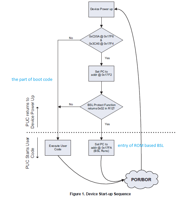
1. Section 1.2 Device Start-up Sequence
Regarding the operation from "Set PC to addr @0x17F2" to "BSL Protect Function returns 0x02 in R12?", customer understands the switching the code to be executed according to the value of R12. Also, Customer understand that it is same behavior as the judgment of 0x17F4 and 0x17F6. Is that correct?
2. BSL430_Low_Level_Init.asm
Regarding above "Figure 1. Device Start-up Sequence", customer would like to understand what " Set PC to addr @ 0x17FA(BSL Runs " means. Since the following description was defined at "0x17FA". That means, code is starting from 0x1000. Is that correct?
> BslEntryLoc .word BSL_Entry_JMP
3. As the result, "JMP C_Branch" is executed. After that, main(void) is carried out in BSL430_Command_Interpreter.c file. Is that correct?
BSL_Entry_JMP JMP   C_Branch                   ; BSL ENTRY AREA
               JMP   BSL_ACTION0
               JMP   $                         ;BSL_ACTION1 unused
               JMP   $                         ;BSL_ACTION2 unused
               JMP   $                         ;BSL_ACTION3 unused
 C_Branch     BR     #_c_int00                 ;BSL_ACTION4 unused
4. Regarding above " JMP BSL_ACTION0", When is the code executed?
5. Regarding those assembly-code, would you share helpful documents/URl with customer, please? Customer was looking for it, however, they were not able to find it.
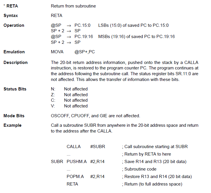
6. Especially, customer was looking for reference-manual for "RETA" command. Although They already checked " MSP430 Assembly Language Tools " document(https://www.ti.com/lit/ug/slau131v/slau131v.pdf), there is not any description for this.Could you clarify it, please ?
Best regards,
Miyazaki