This thread has been locked.
If you have a related question, please click the "Ask a related question" button in the top right corner. The newly created question will be automatically linked to this question.
Hello,
I can't seem to read more than one complete byte in an I2C transmission. I'm using one master and one slave. The MSP430FR2355 is the master and Maxim's DS1307 real-time clock is the slave.
How can I correctly read multiple bytes? Is there anything I'm doing wrong?
Datasheet for the DS1307: cdn.sparkfun.com/.../DS1307.pdf
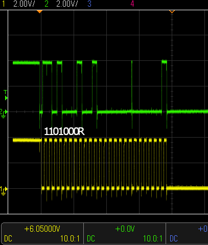
This is what happens when reading one byte (which looks correct):
Fig 1:
These are the memory dumps after reading the data:
(mspdebug) md 0x0540 00540: c0 0f 08 00 00 00 08 00 00 01 01 00 00 00 00 00 |................| 00550: 00 00 00 00 00 00 00 00 00 00 00 00 68 00 ff 03 |............h...| 00560: 68 00 00 00 00 00 00 00 00 00 61 00 08 40 00 00 |h.........a..@..| 00570: ff 3f ff 3f ff 3f ff 3f ff 3f ff 3f ff 3f ff 3f |.?.?.?.?.?.?.?.?| (mspdebug) md 0x056C 0056c: 08 40 00 00 ff 3f ff 3f ff 3f ff 3f ff 3f ff 3f |.@...?.?.?.?.?.?| 0057c: ff 3f ff 3f 01 00 03 00 00 00 00 00 00 00 00 00 |.?.?............| 0058c: 00 00 00 00 00 00 00 00 00 00 00 00 00 00 00 00 |................| 0059c: 02 00 00 00 ff 3f ff 3f ff 3f ff 3f ff 3f ff 3f |.....?.?.?.?.?.?|
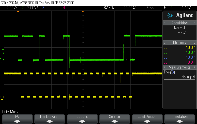
When I reading two bytes, the data line hangs low after the 7th byte of the third frame (second byte to be read):
Fig 2:
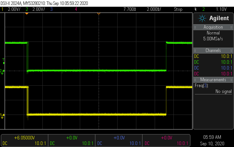
It stays low for about 15ms:
Fig 3:
These are the memory dumps after attempting to read two bytes:
(mspdebug) md 0x0540 00540: c0 0f 08 00 00 00 08 00 00 02 02 00 10 00 00 00 |................| 00550: 00 00 00 00 00 00 00 00 00 00 00 00 68 00 ff 03 |............h...| 00560: 68 00 00 00 00 00 00 00 00 00 61 00 08 40 00 00 |h.........a..@..| 00570: ff 3f ff 3f ff 3f ff 3f ff 3f ff 3f ff 3f ff 3f |.?.?.?.?.?.?.?.?| (mspdebug) md 0x056C 0056c: 08 40 00 00 ff 3f ff 3f ff 3f ff 3f ff 3f ff 3f |.@...?.?.?.?.?.?| 0057c: ff 3f ff 3f 01 00 03 00 00 00 00 00 00 00 00 00 |.?.?............| 0058c: 00 00 00 00 00 00 00 00 00 00 00 00 00 00 00 00 |................| 0059c: 02 00 00 00 ff 3f ff 3f ff 3f ff 3f ff 3f ff 3f |.....?.?.?.?.?.?|
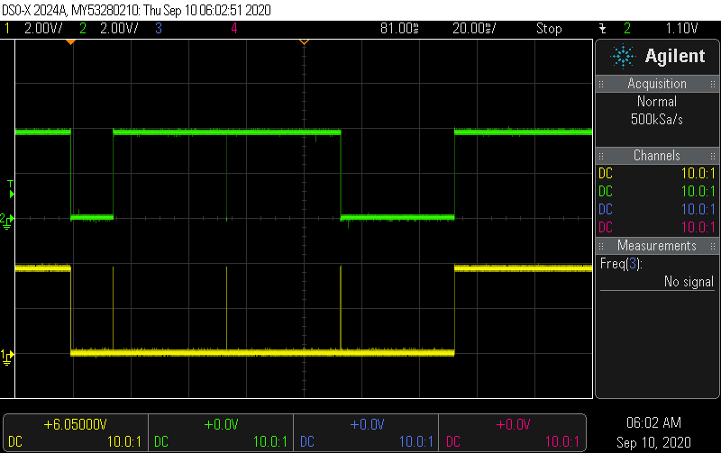
When trying to read five bytes, the SDA line hangs low similar to when reading 2 bytes:
Fig 4:
But there seems to be some attempts to start transmission again in a 130ms time frame before SDA and SCL are released again:
Fig 5:
Here is my code for reading 1 byte. Reading 2 bytes and reading 5 bytes are only different in that NNBytes = 2 and NNBytes = 5.
#include <msp430.h> #include <stdint.h> void Init_GPIO(); const int NNBytes = 1; volatile uint8_t RXData; int main(void) { WDTCTL = WDTPW | WDTHOLD; /* Configure GPIO */ Init_GPIO(); PM5CTL0 &= ~LOCKLPM5; /* Configure P2.3 as input switch to send I2C START command */ P2DIR &= ~BIT3; P2OUT |= BIT3; P2REN |= BIT3; P2IES |= BIT3; P2IFG = 0; P2IE |= BIT3; /* Configure I2C */ P1OUT &= ~BIT0; // Clear P1.0 output latch P6OUT &= ~BIT6; // Clear P6.6 output latch P1DIR |= BIT0; // For LED P6DIR |= BIT6; // For LED P1SEL0 |= BIT2 | BIT3; // I2C pins: SDA | SCL // Configure USCI_B0 for I2C mode UCB0CTLW0 |= UCSWRST; // Software reset enabled UCB0CTLW0 |= UCMODE_3 | UCMST | UCSYNC; // I2C mode, Master mode, sync UCB0CTLW1 |= UCASTP_2; // Automatic stop generated // after UCB0TBCNT is reached UCB0BRW = 0x0008; // baudrate = SMCLK / 8 UCB0TBCNT = NNBytes; // number of bytes to be received UCB0I2CSA = 0x0068; // Slave address UCB0CTL1 &= ~UCSWRST; UCB0IE |= UCRXIE | UCNACKIE | UCBCNTIE; __bis_SR_register(LPM0_bits|GIE); // Enter LPM0 w/ interrupt } #if defined(__TI_COMPILER_VERSION__) || defined(__IAR_SYSTEMS_ICC__) #pragma vector = PORT2_VECTOR __interrupt void Port_2(void) #elif defined(__GNUC__) void __attribute__ ((interrupt(PORT2_VECTOR))) Port_2 (void) #else #error Compiler not supported! #endif { //__delay_cycles(2000); if (P2IFG & BIT3) { P1OUT |= BIT0; // Toggle LED on P1.0 while (UCB0CTL1 & UCTXSTP); // Ensure stop condition got sent //if (UCB0BCNT != NNBytes) UCB0CTL1 |= UCTXSTT; // I2C start condition Uart_puts("START"); uart_putc(0x0A); // new line P2IFG &= ~BIT3; } } #if defined(__TI_COMPILER_VERSION__) || defined(__IAR_SYSTEMS_ICC__) #pragma vector = USCI_B0_VECTOR __interrupt void USCIB0_ISR(void) #elif defined(__GNUC__) void __attribute__ ((interrupt(USCI_B0_VECTOR))) USCIB0_ISR (void) #else #error Compiler not supported! #endif { switch(__even_in_range(UCB0IV, USCI_I2C_UCBIT9IFG)) { case USCI_NONE: break; // Vector 0: No interrupts case USCI_I2C_UCALIFG: break; // Vector 2: ALIFG case USCI_I2C_UCNACKIFG: // Vector 4: NACKIFG UCB0CTL1 |= UCTXSTT; // I2C start condition break; case USCI_I2C_UCSTTIFG: break; // Vector 6: STTIFG case USCI_I2C_UCSTPIFG: break; // Vector 8: STPIFG case USCI_I2C_UCRXIFG3: break; // Vector 10: RXIFG3 case USCI_I2C_UCTXIFG3: break; // Vector 14: TXIFG3 case USCI_I2C_UCRXIFG2: break; // Vector 16: RXIFG2 case USCI_I2C_UCTXIFG2: break; // Vector 18: TXIFG2 case USCI_I2C_UCRXIFG1: break; // Vector 20: RXIFG1 case USCI_I2C_UCTXIFG1: break; // Vector 22: TXIFG1 case USCI_I2C_UCRXIFG0: // Vector 24: RXIFG0 RXData = UCB0RXBUF; // Get RX data //__bic_SR_register_on_exit(LPM0_bits); // Exit LPM0 break; case USCI_I2C_UCTXIFG0: break; // Vector 26: TXIFG0 case USCI_I2C_UCBCNTIFG: // Vector 28: BCNTIFG P1OUT ^= BIT0; // Toggle LED on P1.0 break; case USCI_I2C_UCCLTOIFG: break; // Vector 30: clock low timeout case USCI_I2C_UCBIT9IFG: break; // Vector 32: 9th bit default: break; } } void Init_GPIO() { P1DIR = 0xFF; P2DIR = 0xFF; P1REN = 0xFF; P2REN = 0xFF; P1OUT = 0x00; P2OUT = 0x00; }
What I see is starting the I2C system up to receive data (UCTR reset) but the slave address says transmit. (lsb=0)
Are you referring to a particular figure? (I edited the original post to add figure labels above each figure.)
Or are you referring to line 39 in the code? UCB0I2CSA = 0x0068;
// Slave address
The slave address is 1101000 which is 0x68. My understanding is that if UCTR is 0, the eUSCI module will automatically append 1 to the LSB to receive. Or, should UCB0I2CSA=0xD1=11010001? I did not explicitly set UCTR low because it defaults to low on power up. To me, Figure 1 seems correct in reading 1 byte even though the data is all 0. The transmission in Figure 1 ends with a Nack and a Stop command after reading 1 byte.
However, in Figure 2, the same address is sent with LSB=1 for read, but only 15 bits are read, and SDA and SCL are held low. (i.e. the 8th clock cycle of the second word does not go high and remains low. The last high of SCL is the 7th bit of the second word.)
Hi Gary,
Have you looked at the I2C code examples at http://dev.ti.com/tirex/explore/node?node=AG0ne77m6uNB3UfuU6Ea5g__IOGqZri__LATEST
Srinivas
Srinivas,
I haven't used the driverlib.h library. My code is based off of msp430fr235x_euscib0_i2c_10.c from this link MSP430FR235x, MSP430FR215x Code Examples (Rev. D).
This code implements the same functionality as the code you linked without using driverlib.h. I have pasted the original example code below.
The code I am running is a modified version of the code listed below, and it is listed in the first post of this thread. The main modifications between my code and the code below is as follows:
/* --COPYRIGHT--,BSD_EX * Copyright (c) 2016, Texas Instruments Incorporated * All rights reserved. * * Redistribution and use in source and binary forms, with or without * modification, are permitted provided that the following conditions * are met: * * * Redistributions of source code must retain the above copyright * notice, this list of conditions and the following disclaimer. * * * Redistributions in binary form must reproduce the above copyright * notice, this list of conditions and the following disclaimer in the * documentation and/or other materials provided with the distribution. * * * Neither the name of Texas Instruments Incorporated nor the names of * its contributors may be used to endorse or promote products derived * from this software without specific prior written permission. * * THIS SOFTWARE IS PROVIDED BY THE COPYRIGHT HOLDERS AND CONTRIBUTORS "AS IS" * AND ANY EXPRESS OR IMPLIED WARRANTIES, INCLUDING, BUT NOT LIMITED TO, * THE IMPLIED WARRANTIES OF MERCHANTABILITY AND FITNESS FOR A PARTICULAR * PURPOSE ARE DISCLAIMED. IN NO EVENT SHALL THE COPYRIGHT OWNER OR * CONTRIBUTORS BE LIABLE FOR ANY DIRECT, INDIRECT, INCIDENTAL, SPECIAL, * EXEMPLARY, OR CONSEQUENTIAL DAMAGES (INCLUDING, BUT NOT LIMITED TO, * PROCUREMENT OF SUBSTITUTE GOODS OR SERVICES; LOSS OF USE, DATA, OR PROFITS; * OR BUSINESS INTERRUPTION) HOWEVER CAUSED AND ON ANY THEORY OF LIABILITY, * WHETHER IN CONTRACT, STRICT LIABILITY, OR TORT (INCLUDING NEGLIGENCE OR * OTHERWISE) ARISING IN ANY WAY OUT OF THE USE OF THIS SOFTWARE, * EVEN IF ADVISED OF THE POSSIBILITY OF SUCH DAMAGE. * ******************************************************************************* * * MSP430 CODE EXAMPLE DISCLAIMER * * MSP430 code examples are self-contained low-level programs that typically * demonstrate a single peripheral function or device feature in a highly * concise manner. For this the code may rely on the device's power-on default * register values and settings such as the clock configuration and care must * be taken when combining code from several examples to avoid potential side * effects. Also see www.ti.com/grace for a GUI- and www.ti.com/msp430ware * for an API functional library-approach to peripheral configuration. * * --/COPYRIGHT--*/ //****************************************************************************** // MSP430FR235x Demo - eUSCI_B0 I2C Master RX multiple bytes from MSP430 Slave // // Description: This demo connects two MSP430's via the I2C bus. The master // reads 5 bytes from the slave. This is the MASTER CODE. The data from the slave // transmitter begins at 0 and increments with each transfer. // The USCI_B0 RX interrupt is used to know when new data has been received. // ACLK = default REFO ~32768Hz, MCLK = SMCLK = BRCLK = DCODIV ~1MHz. // // *****used with "msp430fr235x_euscib0_i2c_11.c"**** // // /|\ /|\ // MSP430FR2355 10k 10k MSP430FR2355 // slave | | master // ----------------- | | ----------------- // | P1.2/UCB0SDA|<-|----|->|P1.2/UCB0SDA | // | | | | | // | | | | | // | P1.3/UCB0SCL|<-|------>|P1.3/UCB0SCL | // | | | P1.0|--> LED // // Cash Hao // Texas Instruments Inc. // November 2016 // Built with IAR Embedded Workbench v6.50.0 & Code Composer Studio v6.2.0 //****************************************************************************** #include <msp430.h> volatile unsigned char RXData; int main(void) { WDTCTL = WDTPW | WDTHOLD; // Configure GPIO P1OUT &= ~BIT0; // Clear P1.0 output latch P1DIR |= BIT0; // For LED P1SEL0 |= BIT2 | BIT3; // I2C pins // Disable the GPIO power-on default high-impedance mode to activate // previously configured port settings PM5CTL0 &= ~LOCKLPM5; // Configure USCI_B0 for I2C mode UCB0CTLW0 |= UCSWRST; // Software reset enabled UCB0CTLW0 |= UCMODE_3 | UCMST | UCSYNC; // I2C mode, Master mode, sync UCB0CTLW1 |= UCASTP_2; // Automatic stop generated // after UCB0TBCNT is reached UCB0BRW = 0x0008; // baudrate = SMCLK / 8 UCB0TBCNT = 0x0005; // number of bytes to be received UCB0I2CSA = 0x0048; // Slave address UCB0CTL1 &= ~UCSWRST; UCB0IE |= UCRXIE | UCNACKIE | UCBCNTIE; while (1) { __delay_cycles(2000); while (UCB0CTL1 & UCTXSTP); // Ensure stop condition got sent UCB0CTL1 |= UCTXSTT; // I2C start condition __bis_SR_register(LPM0_bits|GIE); // Enter LPM0 w/ interrupt } } #if defined(__TI_COMPILER_VERSION__) || defined(__IAR_SYSTEMS_ICC__) #pragma vector = USCI_B0_VECTOR __interrupt void USCIB0_ISR(void) #elif defined(__GNUC__) void __attribute__ ((interrupt(USCI_B0_VECTOR))) USCIB0_ISR (void) #else #error Compiler not supported! #endif { switch(__even_in_range(UCB0IV, USCI_I2C_UCBIT9IFG)) { case USCI_NONE: break; // Vector 0: No interrupts case USCI_I2C_UCALIFG: break; // Vector 2: ALIFG case USCI_I2C_UCNACKIFG: // Vector 4: NACKIFG UCB0CTL1 |= UCTXSTT; // I2C start condition break; case USCI_I2C_UCSTTIFG: break; // Vector 6: STTIFG case USCI_I2C_UCSTPIFG: break; // Vector 8: STPIFG case USCI_I2C_UCRXIFG3: break; // Vector 10: RXIFG3 case USCI_I2C_UCTXIFG3: break; // Vector 14: TXIFG3 case USCI_I2C_UCRXIFG2: break; // Vector 16: RXIFG2 case USCI_I2C_UCTXIFG2: break; // Vector 18: TXIFG2 case USCI_I2C_UCRXIFG1: break; // Vector 20: RXIFG1 case USCI_I2C_UCTXIFG1: break; // Vector 22: TXIFG1 case USCI_I2C_UCRXIFG0: // Vector 24: RXIFG0 RXData = UCB0RXBUF; // Get RX data __bic_SR_register_on_exit(LPM0_bits); // Exit LPM0 break; case USCI_I2C_UCTXIFG0: break; // Vector 26: TXIFG0 case USCI_I2C_UCBCNTIFG: // Vector 28: BCNTIFG P1OUT ^= BIT0; // Toggle LED on P1.0 break; case USCI_I2C_UCCLTOIFG: break; // Vector 30: clock low timeout case USCI_I2C_UCBIT9IFG: break; // Vector 32: 9th bit default: break; } }
I have gone back to the original example code, and it seems to work.
What is it about using the push button that breaks it?
>
Uart_puts(
"START"
);
>
uart_putc(0x0A);
// new line
What do these functions do exactly? I don't see any UART setup, so if one of them was e.g. spinning waiting for TXIFG it would never return.
In master-receiver mode, the I2C unit will go ahead and read the first byte without asking, and then halt waiting for you to read RXBUF, which you won't if you're still stuck in the PORT ISR.
Ah yes! The code I posted is incomplete, and there was some UART setup. Those two functions transmit a string and a character using UART.
I think you're right; I removed those UART lines, and I can read 5 bytes after pressing the push button. So, this is why ISRs should be as short as possible ;P
**Attention** This is a public forum