This thread has been locked.
If you have a related question, please click the "Ask a related question" button in the top right corner. The newly created question will be automatically linked to this question.
Tool/software: Code Composer Studio
hi
i am trying to build two compilmatary pwm signal with dead time, from what i read in the datasheet and in the forum i wrote this settings:
TB1CCR0 = 1000; // PWM Period
TB1CCTL1 = OUTMOD_6; // CCR1 reset/set
TB1CCTL2 = OUTMOD_2; // CCR2 reset/set
TB1CCR1 = 800; // CCR1 PWM duty cycle
TB1CCR2 = 750; // CCR2 PWM duty cycle
TB1CTL = TBSSEL__SMCLK | MC__UPDOWN ; // ACLK, up mode, cleBr TBR
TB0CCTL0 |= CCIE; // TBCCR0 interrupt enabled
TB0CCR0 = 800;
//TB0CTL |= TBSSEL__SMCLK | MC__CONTINUOUS; // SMCLK, continuous mode
TB0CTL = TBSSEL__SMCLK | MC__UP | TBCLR; // SMCLK, up mode, clear TBR
i am also using TB0 as ISR.
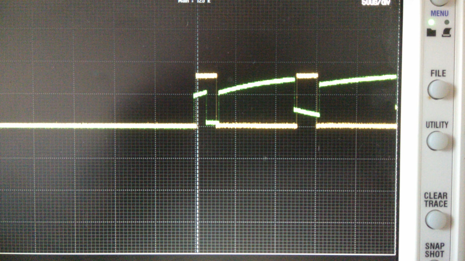
but something does not work here , for some reason the first pulse overlap and if i change TB1CCR1 and TB1CCR2 in the ISR sometimes overlaps occurs.
why?
what am i doing wrong? how can configure it so the overlap wont happen?
thanks a lot.
Hello Ezra,
you need to set the compare latch load events (see section 14.2.4.2.1 in User's Guide)
TB1CCTL1 |= CLLD_2;
TB1CCTL2 |= CLLD_2;
and the CCR load groups (see section 14.2.4.2.2 in User's Guide)
TB1CTL |= TBCLGRP_1;
Best regards,
Tomas
hi,
thanks for your replay.
i tried as you suggested:
TB1CCTL1 |= CLLD_2;
TB1CCTL2 |= CLLD_2;
TB1CTL |= TBCLGRP_1;
TB1CCR0 = 10000; // PWM Period
TB1CCTL1 = OUTMOD_6; // CCR1 reset/set
TB1CCR1 = 5000; // CCR1 PWM duty cycle
TB1CCTL2 = OUTMOD_2; // CCR2 reset/set
TB1CCR2 = 5000; // CCR2 PWM duty cycle
TB1CTL = TBSSEL__SMCLK | MC__UPDOWN ; // ACLK, up mode, cleBr TBR
TB0CCTL0 |= CCIE; // TBCCR0 interrupt enabled
TB0CCR0 = 800;
TB0CTL = TBSSEL__SMCLK | MC__UP | TBCLR; // SMCLK, up mode, clear TBR
but now i get both of the pwm exactly the same and not complemantary.
what do i need to change to get them complimentary and with deat time?
thanks.
TB1CCR0 = 1000; // PWM Period
TB1CCTL1 = OUTMOD_6 | CLLD_2;
TB1CCTL2 = OUTMOD_2 | CLLD_2;
TB1CCR1 = 800;
TB1CCR2 = 750;
TB1CTL = TBSSEL__SMCLK | TBCLGRP_1 | MC__UPDOWN ;
You have to initialize the counter value (before you start the counter) or set correct outputs states for zero counter.
TB1R = 775; // value when both outputs are 0
Complete timer settings:
TB1CCTL1 = 0; // *reset output 1
TB1CCTL2 = 0; // *reset output 2
TB1CTL &= ~MC; // *stop timer
TB1CTL = TBSSEL__SMCLK | TBCLR; // config timer and reset
TB1CCR0 = 1000; // PWM period / 2
TB1CCR1 = 800;
TB1CCR2 = 750;
TB1R = 775; // init timer (start value)
TB1CTL |= TBCLGRP_1; // set groups
TB1CCTL1 = OUTMOD_6 | CLLD_2; // init output 1
TB1CCTL2 = OUTMOD_2 | CLLD_2; // init output 2
TB1CTL |= MC__UPDOWN; // start timer
*Note: can be omitted if this is first setting after reset
**Attention** This is a public forum