This thread has been locked.
If you have a related question, please click the "Ask a related question" button in the top right corner. The newly created question will be automatically linked to this question.
Tool/software: Code Composer Studio
Hello Team,
I faced an error as
MSP430: File Loader: Verification failed: Values at address 0x08170 do not match Please verify target memory and memory map.
MSP430: GEL: File: C:\Users\Lenovo\workspace_v10\Timer_Interrupt\Debug\Timer_Interrupt.out: a data verification error occurred, file load failed.
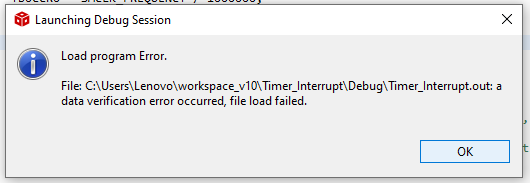
Below is the code i'm trying to load to the target device but getting error as above. I have configured 24Mhz clock to SMCLK and generating interrupt using TimerB0.
Didn't understand what is the mistake and why it is no loading to target. Please help me to solve this error.
#include <msp430.h>
#define DCOCLK_FREQUENCY 24000000
#define MCLK_FREQUENCY DCOCLK_FREQUENCY
#define SMCLK_FREQUENCY DCOCLK_FREQUENCY
unsigned int count=0;
int main(void)
{
WDTCTL = WDTPW | WDTHOLD; // Stop WDT
// Configure GPIO
P1DIR |= BIT0;
P1OUT = 0;
// P2SEL0 |= BIT7; // P2.7 selected as TB0CLK
// Disable the GPIO power-on default high-impedance mode to activate
// previously configured port settings
PM5CTL0 &= ~LOCKLPM5;
P2SEL1 |= BIT6 | BIT7; // P2.6~P2.7: crystal pins
do
{
CSCTL7 &= ~(XT1OFFG | DCOFFG); // Clear XT1 and DCO fault flag
SFRIFG1 &= ~OFIFG;
}
while (SFRIFG1 & OFIFG); // Test oscillator fault flag
__bis_SR_register(SCG0); // disable FLL
CSCTL3 |= SELREF__XT1CLK; // Set XT1 as FLL reference source
CSCTL0 = 0; // clear DCO and MOD registers
CSCTL1 = DCORSEL_7; // Set DCO = 24MHz
CSCTL2 = FLLD_0 + 731; // DCOCLKDIV = 24MHz
__delay_cycles(3);
__bic_SR_register(SCG0); // enable FLL
while (CSCTL7 & (FLLUNLOCK0 | FLLUNLOCK1))
; // FLL locked
CSCTL4 = SELMS__DCOCLKDIV | SELA__XT1CLK; // set XT1 (~32768Hz) as ACLK source
// default DCOCLKDIV as MCLK and SMCLK source
TB0CCTL0 |= CCIE; // TBCCR0 interrupt enabled
TB0CCR0 = SMCLK_FREQUENCY / 1000000;
TB0CTL = TBSSEL__SMCLK | MC_2; // SMCLK, Continuous mode
__bis_SR_register(LPM0_bits | GIE); // Enter LPM0 w/ interrupt
__no_operation(); // For debug
}
// Timer0_B0 interrupt service routine
#if defined(__TI_COMPILER_VERSION__) || defined(__IAR_SYSTEMS_ICC__)
#pragma vector = TIMER0_B0_VECTOR
__interrupt void Timer0_B0_ISR(void)
#elif defined(__GNUC__)
void __attribute__ ((interrupt(TIMER0_B0_VECTOR))) Timer0_B0_ISR (void)
#else
#error Compiler not supported!
#endif
{
count += 1;
if (count == 2)
{
count = 0;
P1OUT ^= BIT0;
}
__bic_SR_register(LPM0_bits);
}
Thanks & Regards
Add this line before you configure the clock:
> FRCTL0 = FRCTLPW | NWAITS_2; // FRAM: 2 wait states
I can't say for sure that this is the cause, but running the FRAM too fast will cause unpredictable behavior.
Hello Vamshi,
Maybe the memory map as specified by the Linker file has some issues?
This e2e thread https://e2e.ti.com/support/tools/ccs/f/81/t/738865 & a CCS debug article has some suggestions on how to find the issue: https://dev.ti.com/tirex/explore/node?node=APy2XbLelxyqBB2Yz0WR.w__FUz-xrs__LATEST
Srinivas
Thank you Bruce,
I will check it now. So you mean to say we can't configure SMCLK to 24Mhz?
i want a timer interrupt at 1 micro second. So i'm tried above code.
Is there any better way for configuring timer tick interrupt at 1 micro second?
Hi Srinivas,
Thank you for reply.
I have cross checked linker files, but everything is fine. I think Bruce have a point i need to check that SMCLK can be configure to 24Mhz or not.
You can configure SMCLK=24MHz. But in the process you will also configure the CPU clock, MCLK=24MHz. In that case, the CPU will try to read FRAM at 24MHz, and it will fail (8MHz max). That line of code forces 2 wait states when reading the FRAM, to slow it down to 8MHz.
As I mentioned over in the other thread, taking an interrupt every 1 microsecond is infeasible, even at 24MHz, since the ISR takes too long. I suspect there's another way to do what you want to do, but I'm not clear what that is.
Hello Bruce,
Thank you, Code is working fine with the line you have suggested below.
> FRCTL0 = FRCTLPW | NWAITS_2; // FRAM: 2 wait states
You told that " taking an interrupt every 1 microsecond is infeasible, even at 24MHz, since the ISR takes too long ". Can you tell me, what is the least possible timer interrupt(in micro seconds) that we can generate?
If i generate an interrupt at 10 micro seconds and toggle DIO in ISR, will that comes out from that ISR within 10 micro seconds? If not please suggest instruction cycles.
Any help would be very thank full.
I usually estimate 20-30 CPU clocks (MCLKs) for a "do-nothing" ISR. The FRAM speed-limit muddies this estimate a little. A 10usec ISR should be feasible if you don't try to do too much. If you plan to use LPM, be sure to check the wakeup time(s) [Ref data sheet (SLASEC4C) Table 5-2].
If it's your goal (as opposed to an experiment) to toggle a pin at 100kHz -- or 1MHz, for that matter -- I would recommend using a timer ("PWM") output, since that requires no CPU resources and would exhibit no software jitter.
Hello Bruce,
Thank you very much for valuable explanation.
One more i want to convey is, i have configured SMCLK to 24Mhz and generated timer interrupt and Toggle DIO in Timer0_B0_ISR. Then i got signal with period of 5.4 milli seconds. Now i'm trying for a period 10 micro seconds at same 24Mhz SMCLK.
Below is the code
#define DCOCLK_FREQUENCY 24000000
#define MCLK_FREQUENCY DCOCLK_FREQUENCY
#define SMCLK_FREQUENCY DCOCLK_FREQUENCY
Then in main I had written
TB0CCTL0 |= CCIE;
TB0CCR0 = SMCLK_FREQUENCY / 1000000;
TB0CTL = TBSSEL__SMCLK | MC_2; // SMCLK, Continuous mode
and in ISR
> P1OUT ^= BIT7;
What change i have to do for getting 10 micro seconds period using timer interrupt at 24Mhz SMCLK ? can you please look into this issue.
> TB0CCR0 = SMCLK_FREQUENCY / 1000000;
This appears to be dividing by 1 million (1usec trigger) not 1 hundred-thousand (10 usec trigger). Try:
> TB0CCR0 = SMCLK_FREQUENCY / 100000UL; // 10usec
-------------
> TB0CTL = TBSSEL__SMCLK | MC_2; // SMCLK, Continuous mode
I think you want Up mode here:
> TB0CTL = TBSSEL__SMCLK | MC_1; // SMCLK, Up mode
-------------
>#define DCOCLK_FREQUENCY 24000000
As a general practice I recommend marking any constant larger than an "int" with "L" or "UL" to prevent the compiler from truncating. Try:
>#define DCOCLK_FREQUENCY 24000000UL
Hello Bruce,
Thank you for everything, I have changed as above. Now it's period is 20 micro seconds.
**Attention** This is a public forum