This thread has been locked.

If you have a related question, please click the "Ask a related question" button in the top right corner. The newly created question will be automatically linked to this question.

MSP430G2553: Usage guidance needed for the Development Tool: MSP430G2xx3 Demo - USCI_B0, I2C Master multiple byte TX/RX

Part Number: MSP430G2553
Other Parts Discussed in Thread: MSP430WARE, MSP-EXP430G2ET

Hi,

I am a noob who is in need of detailed, e.g. step-by-step, guidance as to how to use the Development Tool: MSP430G2xx3 Demo - USCI_B0, I2C Master multiple byte TX/RX

This tool will be found at: Resource Explorer > Software > MSP430Ware (3.80.13.03 )> Development Tools > Devices > MSP4302xx > MSP430G2553 > Peripheral Examples > Register Level > msp430g2xx3_usci_i2c_standard_master.c

My objective it to learn how to use this Development Tool to communicate with an I2C Capacitive Touch Sensor breakout board for the Freescale Semiconductor MRP121.

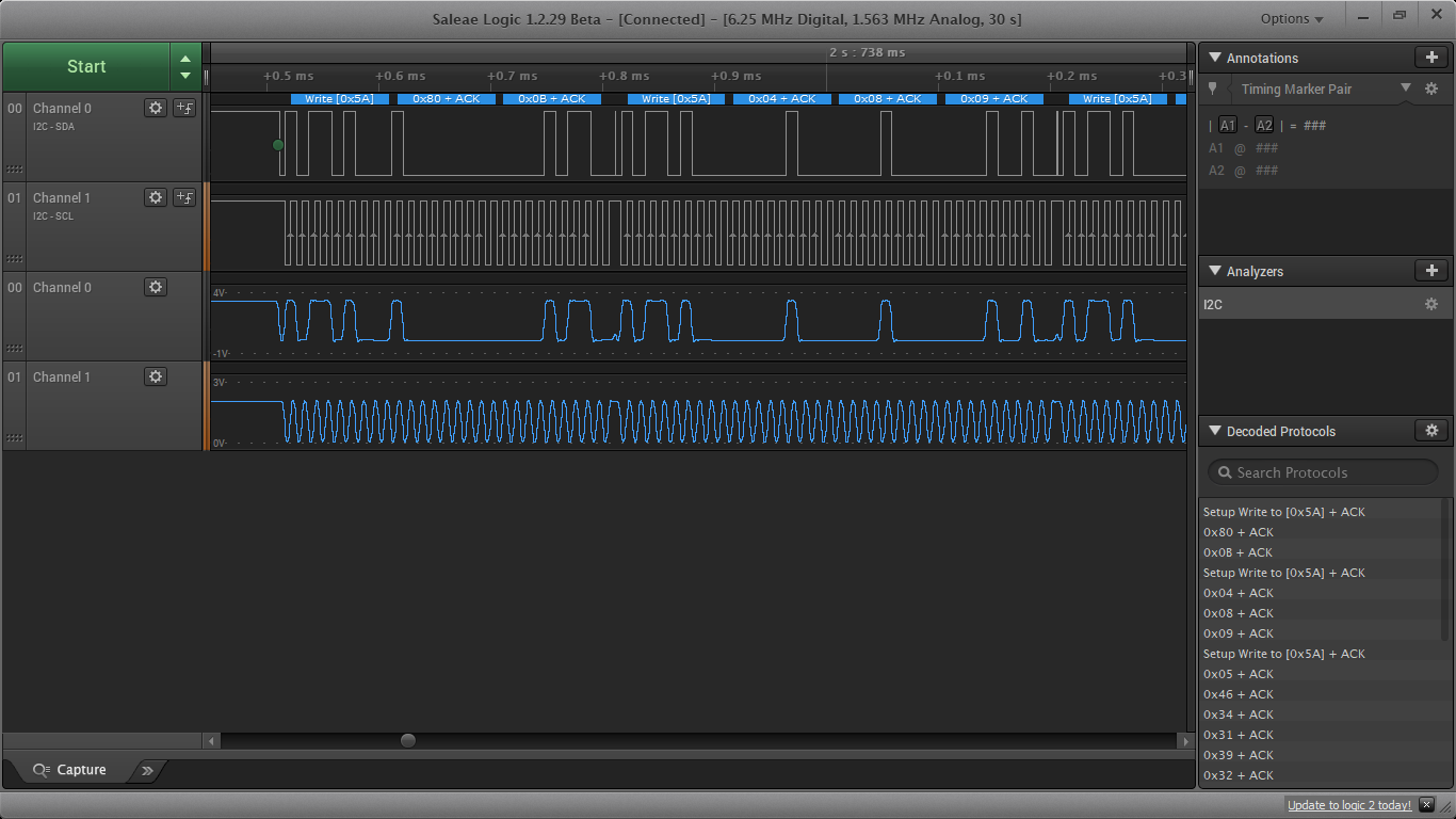
For the development of code for this project I am using a MSP-EXP430g2ET Launch Pad with CCS v10.2.0.00009.  This development system is up and running example programs. I use a Saleae Pro 16 logic analyzer to capture and decode I2C communications.

For this, and projects in the future, production versions will be moved from the Launch Pad to application specific PCB's.

I understand the technical documentation for the MPR121 that explains register usage and the set-up sequence. However, I am not successful at using the I2C Master multiple byte TX/RX development tool to implement the I2C communications with the Freescale Semiconductor MRP121 Capacitive Touch Sensor.

Your help and guidance will be greatly appreciated.

Bob 


  • Hi,

    This is a code to demonstrate to communicate a I2C slave device. What the exact problem when you use the code?

    Do you change the slave address? 

    Does it send anything? Can you post a screenshot of the I2C wave.

    Eason

  • Hi Eason,

    Thanks for replying to my post.

    Answers to your questions:

    1. "This is a code to demonstrate to communicate a I2C slave device. What the exact problem when you use the code?"

    Background:

    a. I understand that the code (MSP430G2xx3 Demo - USCI_B0, I2C Master multiple byte TX/RX) is intended as follows: "I2C master communicates to I2C slave sending and receiving 3 different messages of different length. this is taken from the Description of the Demo.

    b. I have configured the hardware with the pull-up resistors as shown in the Demo code.

    c. The I2C SDA and SCL communications are being captured using a Saleae Pro 16 monitored using Saleae's Logic 1 software.

    Answer to your question #1 "What the exact problem when you use the code?":

    a. I don't understand how to use and the format of the #Define values highlighted in yellow as shown bellow.

    2. "Do you change the slave address?"

    a. Yes, I entered the slave's address as 0x5A, per the slaves documentation. 

    As shown in the green highlight in 1.a image above.
    The result is that the address is written 25 times, each write also writes unknown data data, as shown in the data table from the capture below. 

    Possibly it is writing data as described in Data being defined in the #Define statements? Please see my questions in the image in item 1.a. above.

    b. The format for a Single Byte Write, per the MPR121's Data Sheet, page 22 (attached) is shown as follows:


    3. "Does it send anything? Can you post a screenshot of the I2C wave."

    a. Yes, note the screen shot of the capture and its data table.  Please see item 2 above.

    Thanks, I greatly appreciate you help.

    BobMPR121.pdf

  • You can see the description of the function:

    For read function: it will first write a CMD, then read the bytes you declare in  "count" parameters

**Attention** This is a public forum