This thread has been locked.

If you have a related question, please click the "Ask a related question" button in the top right corner. The newly created question will be automatically linked to this question.

MSP430I2041: MSP430i2041 with EMDC and CCS and read result over I2C

Part Number: MSP430I2041
Other Parts Discussed in Thread: TIDM-3OUTSMTSTRP, , MSP-ISO, UNIFLASH, MSP430F67791, MSP430G2553

Hi.

My name Dung.

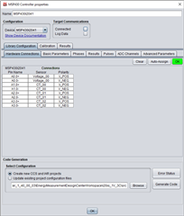
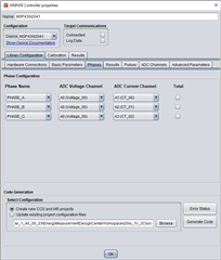
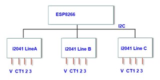
I have project with MSP430i2041 EVM 1 Voltage (990K-2.4K - 220VAC max 250V), 3 Current (CT 1000.1, R = 6.8R max 80A), my design the same TIDM-3OUTSMTSTRP and use CT, not include Relay.

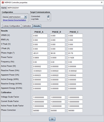
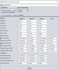
I have some question. On the EMDC when creat project why TI calculator approximately real value.

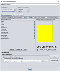
When I calib for MSP430i2041 by EMDC use KIT MSP430F5529LP, if only connect 3 CT to EVM, can read result to EMDC, when I connect 1V 3C to EVM it cannot connect to EMDC. I don't know why (I don't use MSP-ISO).

  • Dung,

    Did you review my feedback to your questions in your previous thread?

    MSP430I2041: Error when I use on Uniflash load image file

    Regards,

    James

  • Hi James. I have view your feedback. I will comback, thread. I thing that error when use Uniflash to load Image. I thing it have complete. If it continouos thread MSP430I2041: Error when I use on Uniflash load image file , this thread is close.

  • Hi Dung,

    If you haven't marked the other thread resolved, please do so. You can copy your EMDC-related questions and my answers into this thread, and then we can continue here.

    Regards,

    James

  • Hi James.

    Other thread I don't have question. This thread I have error when I connect HID to calibration value on KIT MSP430i2041 (EVM). 

    EVM 1 Voltage (990K-2.4K - 220VAC max 250V), 3 Current (CT 1000.1, Rshunt = 6.8R max 80A), my design the same TIDM-3OUTSMTSTRP and use CT, not include Relay.

    When I calibration for MSP430i2041 by EMDC use KIT MSP430F5529LP, if only connect 3 CT (have current thought CT) to EVM, can read result to EMDC (have data result) and add Voltage to EVM it cannot connect to EMDC (no receiver data result on EMDC). I don't know why it can't read data. I don't use MSP-ISO.

    Regards.

  • When I calibration for MSP430i2041 by EMDC use KIT MSP430F5529LP, if only connect 3 CT (have current thought CT) to EVM, can read result to EMDC (have data result) and add Voltage to EVM it cannot connect to EMDC (no receiver data result on EMDC). I don't know why it can't read data. I don't use MSP-ISO.

    Be careful not using the MSP-ISO. If AC line gets connected to the board ground rather than AC neutral, and you're not using MSP-ISO, your PC could get damaged and you could get shocked.

    You're saying that when you connect AC voltage to your board, the communication stops? This could be a power supply issue. How's the board powered? Battery? AC-to-DC power? F5529 LP? Make sure there's no power supply conflicts.

    Make sure your board is powered before or while you are apply voltages to any pins (e.g. connecting sensors, connecting UART pins).

    EVM 1 Voltage (990K-2.4K - 220VAC max 250V), 3 Current (CT 1000.1, Rshunt = 6.8R max 80A), my design the same TIDM-3OUTSMTSTRP and use CT, not include Relay.

    I created this same project in EMDC and had no trouble connecting to the i20xx to view results or calibrate the board.

    • Created new EMDC project with 1V and 3C sensors
    • Configured library based on TIDM-3OUTSMTSTRP
    • Saved EMDC project
    • Generated code
    • Imported code into CCS
    • Programmed i20xx
    • Closed CCS
    • Hooked up i20xx to F5529 LP (HID bridge)
    • Opened MCU in EMDC
    • Clicked Connect
    • Uncalibrated results were shown
    • Started calibration mode without any issues

    Here are some screenshots from my side.

    Regards,

    James

  • Your project run as the same my project Slight smile

    You're saying that when you connect AC voltage to your board, the communication stops? This could be a power supply issue. How's the board powered? Battery? AC-to-DC power? F5529 LP? Make sure there's no power supply conflicts.

    I have test with power from 5529LP and AC-to-DC Power, AC-to-DC module the same TIDM-3OUTSMTSTRP. I have carefully connect Neutral to 0V of EVM. Can you test calibration help me on TIDM-3OUTSMTSTRP. What is your connect?

    When I calibration, I connect TX, RX, GND to P3.4, P3.3 and GND of 5529LP board. Data result when not apply Voltage.

    And if I apply Voltage to EVM, I wait 5 min data not update.

  • I would divide and conquer this issue. I don't think it's an EMDC issue but a power supply issue. Without hooking anything up to AC, use the F5529 LP or a bench supply to power your board. The EMDC communication should work, and you should be able to enter the calibration mode. If that works, it indicates that your power supply is causing the device to stop communicating when AC is connected and you can start debugging that rather than the communication.

  • Now, I can't work on the i2041 for my project, because I don't understand why it can't be calibration. I switched to another IC for EVM, because i don't have time for test. If in future I have time maybe I can test and use it. MSP430i2401 and msp430F67791 I am sorry it don't work for my project. I have more time for it but it is not as expected.

    Thank you so much, James.

  • Hi James.

    The TI have solution for customer to design EVM. Why TI don't integration example calib value calculator in Code flow value of customer designed.

  • Hi Dung,

    The manual calibration process is complex and requires an accurate test source to apply precise voltages, currents and phase angles to the board. The EMDC GUI still requires a test source but will easily perform the calibration process. Then, you can use the applied calibration factors in your final design by either updating those factors in your CCS project or sending them over UART from a host MCU or processor in the system.

    For more details about the calibration calculations, refer to the following thread.

    MSP430i2041: Need EMDC calibration factor calculation details

    Regards,

    James

  • Hi, Jame.

    I thing when read full result Voltage mode Common ( 1V 3 CT), in EMDC mcu is >80%, but real when apply Voltage i thing MCU is overload => I can't read result and calibration it.  Then i readl Vrms, Irms, V Peak, I Peak, Active Power, Active Energy. I can calibration it.

    Now a read result over I2C, but it not read data. i use esp8266 on arduino.

    Start i write 55 AA 06 04 01 01 01 07 00, when read i write 55 AA 06 04 80 00 01 0D 00 ( VRMS PHASE A). result is 0189040E, when i change read Irms PhaseA and V, I of other Phase the same result.

    I don't understand. maybe wrong write I2C?  I Read mode Device 0x0A is '0' => IDLE in evm_start()

    Fullscreen
    1
    2
    3
    4
    5
    6
    7
    8
    9
    10
    11
    12
    13
    14
    15
    16
    17
    18
    19
    20
    21
    byte evm_config(uint8_t device,uint8_t cmdRW, uint8_t cmdValue)
    { // 55 AA 06 04 CMD_CONFIG_MODE cmdRW cmdValue crcl crch
    byte byte_in,error;
    prepare_evm_write(CMD_CONFIG_MODE,cmdRW,cmdValue,6);
    Wire.beginTransmission(device);
    Serial.print(" Device: "); Serial.print(device,HEX); Serial.print(" ");
    for(byte i=0;i<9;i++) {
    Wire.write(evm_write_message[i]);
    if(cmdRW==CMD_WRITE)Serial.print(evm_write_message[i],HEX);
    }
    error = Wire.endTransmission();//Wire.endTransmission();
    if(cmdRW==CMD_READ){
    Wire.requestFrom(device, 1);
    byte_in = Wire.read();
    Serial.print(byte_in,HEX);
    }
    Serial.println(" ");
    return error;
    }
    void evm_start(){
    XXXXXXXXXXXXXXXXXXXXXXXXXXXXXXXXXXXXXXXXXXXXXXXXXX

  • Hi Dung,

    I thing when read full result Voltage mode Common ( 1V 3 CT), in EMDC mcu is >80%, but real when apply Voltage i thing MCU is overload => I can't read result and calibration it.  Then i readl Vrms, Irms, V Peak, I Peak, Active Power, Active Energy. I can calibration it.

    I'm sorry, but I don't understand this. Are you saying that you can read the values when no voltage is applied but you cannot read values when voltage is applied? That shouldn't matter unless there's a power supply conflict. If you're using the MSP-ISO, make sure you're not using the isolated power supply for 3V3 if your board already has an AC/DC to 3V3 supply.

    Start i write 55 AA 06 04 01 01 01 07 00, when read i write 55 AA 06 04 80 00 01 0D 00 ( VRMS PHASE A). result is 0189040E, when i change read Irms PhaseA and V, I of other Phase the same result.

    For these commands, you can check the protocol in the latest EMDC Technology Guide (v1.40 as of today). Make sure you're changing the Phase ID byte in the command.

    I don't understand. maybe wrong write I2C?  I Read mode Device 0x0A is '0' => IDLE in evm_start()

    I'm not sure about the Arduino code. Perhaps you could post that on an Arduino forum. I would also recommend just using one of our I2C code examples from TI Resource Explorer on the i20xx with dummy data to get the I2C communication working separately from the EMDC project. Then, you can work on integrating the I2C code into your EMDC project when it's working.

  • Hi James.

    I'm sorry, but I don't understand this.

    When I creat new project EVM with all parameter (0x80-0x8B) in mode 1V 3 CT, data result can connect with EMDC when AC voltage don't connect. When I connect AC Voltage to EVM => can't read result to calibration by EMDC.

    If I creat project with VRMS, IRMS, Vpeak, Ipeak, Active power, Energy Power mode 1V 3 CT, I can calibration EVM over EMDC.

    I'm not sure about the Arduino code. Perhaps you could post that on an Arduino forum. I would also recommend just using one of our I2C code examples from TI Resource Explorer on the i20xx with dummy data to get the I2C communication working separately from the EMDC project. Then, you can work on integrating the I2C code into your EMDC project when it's working.

    Can you send to me example project Communication I2C between MSP430F5529LP with EVM MSP430i2041. After read result over I2C 5529LP send data debug to PC by UART. I want test I2C read data is Ok with MSP430Fxx. Please help me.

    My project need send data to Server over Wifi Internet. 


    Thank you so much.

  • When I creat new project EVM with all parameter (0x80-0x8B) in mode 1V 3 CT, data result can connect with EMDC when AC voltage don't connect. When I connect AC Voltage to EVM => can't read result to calibration by EMDC.

    If I creat project with VRMS, IRMS, Vpeak, Ipeak, Active power, Energy Power mode 1V 3 CT, I can calibration EVM over EMDC.

    The EMDC code programmed on the EVM must match the EMDC project. If they don't the communication may not work correctly.

    Can you send to me example project Communication I2C between MSP430F5529LP with EVM MSP430i2041. After read result over I2C 5529LP send data debug to PC by UART. I want test I2C read data is Ok with MSP430Fxx. Please help me.

    Check out my earlier comments. I'd recommend starting with the I2C code examples in TI Resource Explorer (inside CCS or at dev.ti.com). Like I mentioned earlier, you'll want to split this effort up and make incremental progress.

  • You did the I2C communication in measurement with the i2041. Structure to write read data with i2041 like. Can you write a sample code to initialize the i2041 to operate and read measured voltage or current data?

    Can you send to me example code to read data from i2041 in this application.

    What is address of VRMS, IRMS, and other data when i want read?

    Usually, i read and write to Eeprom, form for write (SlaveAdd, Address & read or write, data write or data to read).

  • You did the I2C communication in measurement with the i2041.

    I'm not sure what you mean.

    Can you send to me example code to read data from i2041 in this application.

    You can find i20xx I2C example code in TI Resource explorer inside CCS or at dev.ti.com.

    What is address of VRMS, IRMS, and other data when i want read?

    These are just variables stored in RAM that you can use with I2C to send the data to a host.

  • Hi James Evans.

    I use I2C to read result EVM from i2041. I write on MSP430G2553. MSP430G2553 is mater I2C will read data evm of multi device i2041 (add 0x0A). but my code read result only 00 FF FF FF FF FF FF FF FF FF FF . Please check for me, i have send I2C_Master_Write(SLAVE_ADDR, MasterType0, TYPE_0_LENGTH);  // {0x55,0xAA,0x06,0x04,0x01,0x01,0x01,0x07,0x00};   before read data   {0x55,0xAA,0x07,0x04,0x80,0x00,0x00,0x00,0x84,0x00};

    Fullscreen
    1
    2
    3
    4
    5
    6
    7
    8
    9
    10
    11
    12
    13
    14
    15
    16
    17
    18
    19
    20
    21
    //******************************************************************************
    // MSP430G2xx3 Demo - USCI_B0, I2C Master multiple byte TX/RX
    //
    // Description: I2C master communicates to I2C slave sending and receiving
    // 3 different messages of different length. I2C master will enter LPM0 mode
    // while waiting for the messages to be sent/receiving using I2C interrupt.
    // ACLK = NA, MCLK = SMCLK = DCO 16MHz.
    //
    //
    // MSP430G2553
    // -----------------
    // /|\ | P2.6|--- XIN
    // | | | |
    // ---|RST | 32kHz
    // | | |
    // | P2.7|--- XOUT
    // | P1.1|<------- Receive Data (UCA0RXD)
    // | P1.2|-------> Transmit Data (UCA0TXD)
    // | P1.6|<------- Receive Data (UCB0SCL)
    // | P1.7|-------> Transmit Data (UCB0SDA)
    //
    XXXXXXXXXXXXXXXXXXXXXXXXXXXXXXXXXXXXXXXXXXXXXXXXXX
     

    I have read your write on https://e2e.ti.com/support/microcontrollers/msp-low-power-microcontrollers-group/msp430/f/msp-low-power-microcontroller-forum/844030/ccs-msp430i2040-emdc-i2c-communication-with-evm430-i2040s/3121142?tisearch=e2e-sitesearch&keymatch=msp430i2041%2520i2c#3121142  18/10/2019  4:32 PM. Please you can send to me project you write read data over i2c ok.

    Thank so much.

  • This thread should contain details about making changes to use I2C.

    MSP430I2040: Interfacing the MSP430i2040S Sub metering EVM on I2C

  • Hi James. 

    I write code with f5529. My project  read evmi2041 (multi device) over I2C and send to PC by UART, now i have connect one device EVM, but data result not true. Please check for me

    Fullscreen
    1
    2
    3
    4
    5
    6
    7
    8
    9
    10
    11
    12
    13
    14
    15
    16
    17
    18
    19
    20
    21
    //******************************************************************************
    // MSP430F552x Demo - USCI_B0, I2C Master multiple byte TX/RX
    //
    // Description: I2C master communicates to I2C slave sending and receiving
    // messages of different length. I2C master will enter LPM0 mode
    // while waiting for the messages to be sent/receiving using I2C interrupt.
    // ACLK = NA, MCLK = SMCLK = DCO 16MHz.
    //
    // /|\ /|\
    // MSP430F5529 4.7k |
    // ----------------- | 4.7k
    // /|\ | P3.1|---+---|-- I2C Clock (UCB0SCL)
    // | | | |
    // ---|RST P3.0|-------+-- I2C Data (UCB0SDA)
    // | |
    // | P3.3|-------+-- UART TX (UCA0 TXD)
    // | |
    // | P3.4|-------+-- UART RX (UCA0 RXD)
    // | |
    // | |
    //
    XXXXXXXXXXXXXXXXXXXXXXXXXXXXXXXXXXXXXXXXXXXXXXXXXX

    Data read result.

  • Are you connected to AC voltage? If you're not, that could be why the results are zero. Also, check your function in 'emDCCommandHandlers.c'. It should look something like this for VRMS. Your data read packets seem to be longer than necessary.

    void CommandHandler_transmitVRMS(Packet_t *packet,
                                     uint8_t phaseID,
                                     uint8_t *vrms)
    {
        packet->length = 8;
        packet->payload[0] = COMMAND_HANDLER_EM_GUI_ID_BYTE;
        packet->payload[1] = COMMAND_HANDLER_VRMS_ID;
        packet->payload[2] = COMMAND_HANDLER_WRITE_CMD;
        packet->payload[3] = phaseID;
        packet->payload[4] = vrms[0];
        packet->payload[5] = vrms[1];
        packet->payload[6] = vrms[2];
        packet->payload[7] = vrms[3];
    
        Comm_writePacket(packet);
    }
  • I want read VRMS result, i have sent to device command of VRMS, but result i read not VRMS. In command read is 0x89. You can viewer value of command I send to device change from 0x80 - 0x84, but read result comback have command 0x89.

    I thing have problem is code or connect. I have connect F5529LP 4 wire (3.3V SDA, SCL, GND). Can you help me check my code in my write 20-05-2021.

    How long after write command to slave device, I can read data result. In project EVM need to use Request PIN? Do you have code example read data result from i204x over I2C. Can you send to me by reply or send to email dungnv@lctech.vn.

    Thank you so much.

  • I'd recommend digging into the code and see why the return command is wrong. Perhaps the command that's sent from the F5529 is incorrect.

**Attention** This is a public forum