This thread has been locked.

If you have a related question, please click the "Ask a related question" button in the top right corner. The newly created question will be automatically linked to this question.

Regarding SPI MISO waveform level problem.

Other Parts Discussed in Thread: CSD

  I am using a MSPEXPF5438a  board and soldered SD card to it on the SPI ports. I am able to get the clock on the SPI but my MISO level waveform is not right. I am attaching the waveform for this. What seems to be the problem?
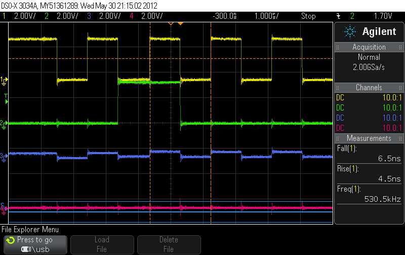
Waveform Legend:

1) Yellow : Clock

2) Green : MOSI

3) Purple: MISO

4) Pink : Chip select.

  • I would say that the problem is in the SD card which is not sending data. Could it be that it needs an external pull up?

  • Hmm. Maybe, but in the application note http://www.ti.com/lit/an/slaa281b/slaa281b.pdf nothing is mentioned about pull ups. Also in case of MSPEXPF5529 experimenters board no pull ups are provided in the design file.

  • Another possibility is that, because of bad configuration or hardware failure, the MISO pin on the MSP is outputting a "0" and colliding with the data from the SD card.

  • I tried by toggling the pin in the GPIO mode and it toggles properly.

  • In the SPI mode, with no SD card, did you try to put a "1" on the MISO? It should be possible, since the pin should be an input.

  • How can I put a "1" on the MISO when its an input?

  • Using an external pullup. If the pullup succeeds putting the pin into "1", the pin is an input. If not, there is a config. error and it is an output.

  • Hah!! Should have thought about that :) . Let me check this.

  • Indeed, the MISO line look slike crosstalk from clock and no signal at all.

    It may be that the SD card isn't properly selected and therefore doesn't output anything.

    Note that floating lines are detected as 'low' on scopes.

    Another thing I noticed: until initialized, the maximum clock frequency for SD cards is 400kHz. Your clock has 530kHz.

    And IIRC, afterpower-on, the card requires several dummy clock pulses on the clock before it is ready to receive a command.

    And a very simple question: is your SD card powered properly?

  • Ok. I setup a pull up for MISO and MOSI lines. The MISO now shifts between 3 to 3.5 mv.

    The purple MISO is pulled high. And when data is transferred I am not sure whether its cross talk or the signal is just struggles to go up.

  • What does selecting an SD card mean? I didn't get it. Do you mean selecting SPI mode?

    I will check on the clock frequency. I made a mistake there.

    Right now my initial power up sequence is as follows:

    1) Send 0xFF pulses for 10 cycles.

    2) Send 0x40,0x00,0x00,0x00,0x00,0x95 data.

    I verified these 2 data by setting up the SPI triggers on the DSO, but still the MISO is dead. I tried to send both of them on loop but nothing happens.

    Also I think it might be noise as I changed the ports for the above and also I changed the chip too.

    My setup is

        UCB3CTL0 = UCMSB|UCMST|UCSYNC|UCCKPL|UCCKPH;

    I am setting  UCCKPH because if I don't I am missing one bit.

  • Also what do you mean by powering up the SD card. I soldered the VCC of the board to it. Any other suggestions? Should I power it externally?

  • Selecting it means that CS to the card is being asserted (low).

    BTW, did you put a decoupling capacitor for VCC and a pullup for CS close to the card?

    Do you see CD going low when the card is in? For some applications I saw that CD is connected to GND

  • I have not put a decoupling capacitor and a pullup for CS.

    The microSD card is inside an adapter card.

    When I put in the SD card the CS goes high.

  • Try to put at least the decoupling capacitor, as close to the SD Card socket as possible.

    Check if CS goes low when your software talks with the card.

  • Gautam Bhat said:
    What does selecting an SD card mean?

    Each and every SPI device has a chip select signal. It synchronizes the SPI bus to the beginning of a byte (there are no start or stopbits, so without it you could be one bit off and stay off forever). It also synchronizes the beginning of a high-level transfer. And only the SPI slave that has its CS signal low may talk to SOMI. All others have to remain silent.

    CS is the third pin on the standard SD card socket (don't ask me form which side).

    The procedure is:

    pull CS high, then send the 10 dummy bytes.

    Now pull CS low, send the 0x95 command
    wait for response (you'll need to send further dummy bytes until you get it or get a timeout)
    then pull CS high again and send another dummy byte.
    Then CS low again, send ACMD41, wait for response, pull CS high, send dummy byte.
    If ACMD41 fails, try CMD1 instead, as it seems to be an MMC card and no SD card.
    You may try CMD1 even if ACMD41 worked, and if it fails, you have a micro SD card. If both work, it is a standard or mini SD card.

    And so on.

    After this, I also read the CSD and if it contains data I can handle (e.g. 512 byte read/write size) I accept the card, set it to idle mode and raise teh SPI coloch for further transfers.

    This is how MMC and SD cards work on my 5438, 1611 and the ATMega128.

  • I have the same problem.
    I setup a pull up for MISO and MOSI lines.
    I tried by toggling the pin in the GPIO mode and it toggles properly.

    MISO is still wrong.
    MISO is always high and have a little crosstalk by clock.
    SPI clock speed is 250K

    SD card is SanDisk (UHS-I)(32GB)

    Any idea ?
    How Gautam Bhat solve the problem ?
  • I have the same problem.
    SPI speed is 250K
    I pretty sure all pin are OK. (MOSI/Clock/Chip select)
    All waveform looks good.
    SD voltage is 3.3V

    SPI send 80 clock with MOSI high and CS high
    SPI send 0x40,0x00,0x00,0x00,0x00,0x95
    SPI continue send more clock to get response.
    But SD Card never response R1.

    MISO is always high and has a little crosstalk by clock.
    MISO has pull -up.

    Any idea ?
    Does Gautam Bhat solve the problem ?
  • I have solved the problem but I don't know why I have not updated this thread.


    As far as I remember I think I sent more dummy bytes to get the response. Also can you lower the clock speed to 100KHz and check?

    I had written some test code during that time. Please verify by checking the code attached.

    4743.spi_test_ads.c
    #include <msp430x552x.h>
    #include <stdint.h>
    #include "hal_pmm.h"
    
    #define CS			(BIT7)
    #define SPI_CLK 	(BIT0)
    #define SPI_MOSI 	(BIT4)
    #define SPI_MISO	(BIT5)
    
    #define CS_PxSEL	(P3SEL)
    #define CS_PDIR		(P3DIR)
    #define CS_PxIN		(P3IN)
    #define CS_PxOUT	(P3OUT)
    
    #define SPI_PxSEL	(P4SEL)
    #define SPI_PxDIR	(P4DIR)
    #define SPI_PxIN	(P4IN)
    #define SPI_PxOUT	(P4OUT)
    
    
    #define TXBUFREADY (UCA1IFG&UCTXIFG) //Ready if 1. Buffer empty.
    #define RXBUFREADY (UCA1IFG&UCRXIFG) //Ready if 1. Data present in buff.
    
    #define ISBUSY	(UCA1STAT&UCBUSY)
    
    
    #define DUMMY_BYTE 	0xFF
    
    #define CMD0		0
    #define CMD1		1
    #define CMD8		8
    #define CMD9		9
    #define CMD10		10
    #define CMD55		55
    
    uint8_t dummy_string[] = {0xFF};
    uint8_t test_string[] = {0xaa};
    uint8_t spi_cmd_string[6];
    
    #define START_BIT 	(1<<6)
    #define STOP_BIT  	BIT0
    
    
    inline void set_cs_high() {
    	P3OUT |= CS;
    }
    
    inline void set_cs_low() {
    	P3OUT &= 0x7F;
    }
    
    inline void set_bandwidth(unsigned int bw) {
    	UCA1BR0 = (bw & 0xFF);
    	UCA1BR1 = (bw>>8);
    }
    
    
    inline void set_spi_clk() {
    	UCA1CTL1 |= UCSSEL_2;
    }
    
    inline void reset_state_machine() {
    	UCA1CTL1 |= UCSWRST;
    }
    
    inline void set_state_machine() {
    	UCA1CTL1 &= ~UCSWRST;
    }
    
    inline void spi_init() {
    
    	SPI_PxSEL = ((SPI_CLK)|(SPI_MOSI)|(SPI_MISO));
    	SPI_PxDIR |= SPI_CLK;
    	SPI_PxDIR |= SPI_MOSI;
    	SPI_PxDIR &= ~SPI_MISO;
    	SPI_PxOUT |= ((SPI_CLK)|(SPI_MOSI));
    
    
    	UCA1CTL0 = UCMSB|UCMST|UCSYNC|UCCKPL;
    	reset_state_machine();
    
    	set_spi_clk();
    
    	set_bandwidth(3);
    	set_state_machine();
    }
    
    inline void send_dummy_byte(int times) {
    	
    	unsigned int i = 0;
    
    	for(i = 0;i<times;i++) {
    		while(!(UCA1IFG & UCTXIFG))  //Loop until Tx Buf is empty.
    			;
    		
    		UCA1TXBUF = DUMMY_BYTE;
    	}
    }
    
    
    inline void create_sd_command(uint8_t cmd,uint32_t command_arg) {
    	spi_cmd_string[0] = START_BIT|cmd;
    	spi_cmd_string[1] = (command_arg)>>24;
    	spi_cmd_string[2] = (command_arg)>>16;
    	spi_cmd_string[3] = (command_arg)>>8;
    	spi_cmd_string[4] = (command_arg);
    	spi_cmd_string[5] = 0xFF;
    }
    
    inline void sd_write(unsigned char *buff,int bufflen) {
    	unsigned int i = 0;
    
    	for(i = 0;i<bufflen;i++) {
    		while(TXBUFREADY==0)  //Loop until Tx Buf is empty.
    			;
    		
    		UCA1TXBUF = buff[i];
    	}
    
    	while(TXBUFREADY==0)  //Loop until Tx Buf is empty.
    		;
    
    	//set_cs_high();
    }
    
    inline void send_response_dummy_bytes() {
    
    	while(ISBUSY){ //Loop until empty.
    		;
    	}
    	UCA1TXBUF = DUMMY_BYTE;
    }
    
    inline uint8_t sd_read() {
    	char ch;	
    	
    	while(ISBUSY);
    		
    	ch = UCA1RXBUF;
    						
    	return ch;	
    }
    
    inline uint8_t sd_get_response() {
    	send_response_dummy_bytes();
    	return sd_read();
    }
    
    inline void send_idle_startup_cycles() {
    	set_cs_high();
    	send_dummy_byte(100);
    }
    
    
    inline void sd_send_cmd() {
    	uint8_t i = 0;
    	unsigned char ch;
    
    	while(1) {
    		sd_write(spi_cmd_string,6);
    		i = 0;
    		while(i++<=10) { 
    			ch = sd_get_response();
    			if(!ch) 
    				goto done;
    		}
    	}
    
    done:
    	;
    }
    
    inline void glow_green() {
    	while(1) {
    		P5OUT ^= 0x01;
    		__delay_cycles(50000);
    		__delay_cycles(50000);
    	}
    }
    
    inline void glow_blue() {
    	while(1) {
    		P5OUT ^= 0x02;
    		__delay_cycles(50000);
    		__delay_cycles(50000);
    	}
    }
    
    inline uint8_t sd_init() {
    	int i = 0;
    	char ch;
    
    	send_idle_startup_cycles();
    
    	/* Send CMD0 */
    	create_sd_command(CMD0,0);
    	spi_cmd_string[5] = 0x95;
    
    	set_cs_low();
    	sd_write(spi_cmd_string,6);
    	i = 0;
    	while(i++<=8) {
    		ch = sd_get_response();
    		if(ch == 1)  {
    			set_cs_high();
    			break;
    
    		}
    	}
    	
    	/* Send CMD8 */
    	create_sd_command(CMD8,0x1AA);
    	spi_cmd_string[5] = 0x87;
    	while(1) {
    		set_cs_low();
    		sd_write(spi_cmd_string,6);
    		i = 0;
    		while(i++<=10) {
    			ch = sd_get_response();
    			if(ch == 1)  {
    				send_dummy_byte(20);
    				set_cs_high();
    
    				goto cmd8out;
    			}
    		}
    		set_cs_high();
    	}
    
    cmd8out:
    //	send_dummy_byte(1000);
    	
    	/* Send CMD1 */
    	while(1) {
    		set_cs_low();
    		/*create_sd_command(CMD55,0x0);
    		sd_write(spi_cmd_string,6);*/
    		
    		create_sd_command(CMD1,0x40000000);
    		sd_write(spi_cmd_string,6);
    		//send_dummy_byte(20);
    		set_cs_high();
    
    		set_cs_low();
    		i = 0;
    		while(i++<=100) {
    			ch = sd_get_response();
    			if(!ch) {
    				set_cs_high();
    				goto out;
    			}else if(ch == 1) {
    				set_cs_high();
    				send_dummy_byte(8);
    				set_cs_low();
    
    			}
    		}
    		set_cs_high();
    	}
    
    
    out:
    	
    	/* Send CMD10 */
    	create_sd_command(CMD10,0);
    	set_cs_low();
    	sd_send_cmd();
    	set_cs_high();
    
    end:
    	i = 0;
    	set_cs_low();
    	while(i<22) {
    		ch = sd_get_response();
    		i++;
    	}
    	set_cs_high();
    
    	glow_blue();
    	return 1;
    }
    
    
    int main(int argc,char **argv) {
    	WDTCTL = WDTPW | WDTHOLD;
    
    	P5DIR |= 0x03; //LED
    
    	P3DIR |= CS;	//Chip Select.
    	
    	SetVCoreUp(PMMCOREV_3);
    
    	spi_init();
    	sd_init();
    
    	set_cs_high();
    	
    	__bis_SR_register(GIE);
    
    	while(1) 
    		__no_operation();
    	
    	return 0;
    }


    -Gautam.

  • Ronnie,

    The SPI speed could possibly be causing the issue you are seeing. Please let us know if Gautam's suggestions help solve your problem.

    Regards,
    Ryan
  • 250k SPI speed is okay. The limit before the card is initialized is 400kHz. After this, 20 or 25MHz are the limit.
    I've noticed that some manufacturers have removed serial support from the 'newer' cards (SDHC, SDXC and the UHS cards). I wouldn't expect if from an original SanDisk device, btu maybe... After all, reading 32GB with 25MHz serial clock takes many hours (>3hrs plain data time plus communication overheads and fetching/writing times).
    Try to get it to work with an old 2GB standard SD card first, then expand to an SDHC card.

**Attention** This is a public forum