This thread has been locked.
If you have a related question, please click the "Ask a related question" button in the top right corner. The newly created question will be automatically linked to this question.
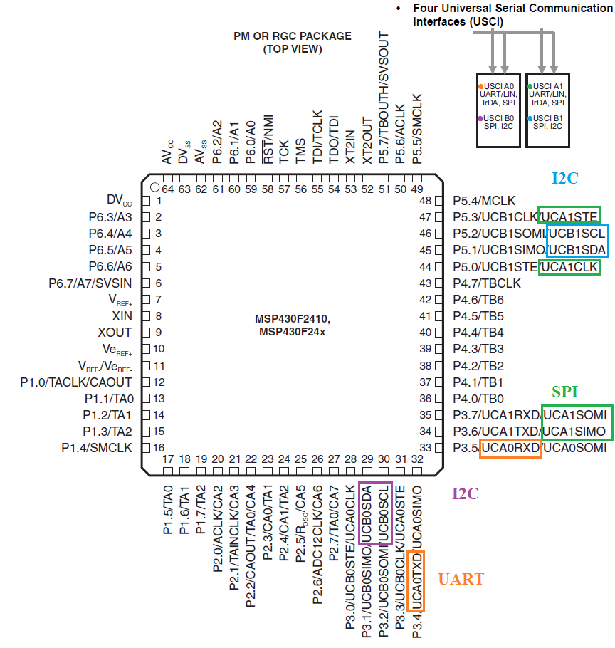
I am trying to confirm the possibility of assigning the following USCI's interfaces in a proposed application on a single MSP430F247: two I2C, one SPI and one UART interfaces. The colored picture below is self explanatory.I am using the MSP430F247 as an example but this is really about TI's hardware convention not just that IC. So yes, I scrutinized the datasheet and the specific user guide carefully. I have 90% confidence that this is not violating any hardware partitioning in the MSP but one of the diagram in the datasheet cast a shadow of doubt. I reproduced it on the top right of my picture below for convenience. It shows two boxes : ( USCI A0 + USCi B0 ) in one box and ( USCI A1 + USCi B1 ) in a second box. Is this apparent partitioning indicative of a hardware limitation ?
The proposed four interfaces don't seem to have any pin assignment issue and the register map addresses do not clash either. Finally the datasheet says 4 interfaces (but in which logical OR/AND configuration ?). Better be 100% sure than having to redo a board design.
I'm quite sure you've got this right. What I would recommend though, if possible, is to experiment before you spin a board. It might save you a lot of heartache. The MSP-TS430PM64 is a pretty nifty development board for those particular chips (or MSP-FET430U64 if you don't already have a programmer). I've also used some of the MSP-EXP boards; they're a lot cheaper.
Greg, thanks for the good advice and the quick reply. I am going to get the MSP-FET430U64 bundle.
Clemens, ok thank you. i see from the datasheet vector table how USCI Ax and Bx share interrupt vectors. This means having to poll interrupt flags in the interrupt handler routines to find the source(s), a negligible overhead. But even if there were independent vectors for each existing interface assuming worst case that my application requires three interfaces to run concurrently (two I2C and one SPI), how to know that the MSP is running out of CPU bandwith to service all the active routines. I guess those interfaces have a flag for that which will be useful when debugging.
Greg, you word of caution on DMA availability and errata made me re-check my MSP selection. The two I2C interfaces will be used in TX mode only (one is for a small 128*64 display, the other is insignificant) and the SPI and UART interfaces will have to support RX/TX with moderate amount of data transfer. The UART is for communicating with a second smaller higher performance MSP430FR. That interface will only carry low rate results. The errata sheet for that second MSP has dma7 and dma11.
But the above MSP has no DMA channel, I just found. It seems DMA is a must have for updating the screen memory (8 KB) to the display driver ?
Hi Howard,
As indicated above already your configuration doesn't violate the hardware partitioning. Just for your information the two boxes are partitioned this way as there are instances of the same part (F23x) that only have USCI A0 and USCI B0, while parts such as F247 add USCI A1 and USCI B1.
On the need for DMA I'd go with Greg and say this depends on your application, on the one hand
Greg Fundyler said:how fast you need to update the display and how many clock cycles you can spare to do so
and what other application requirements you have, i.e. what the MCU does in the meantime.
Best regards,
Britta
**Attention** This is a public forum