A new system doesn’t always work properly on the first try when you are trying to drive a motor with a newly designed PCB system.
For example, the motor may not start up, or does not operate smoothly.
The debugging process involves analyzing your system and gathering information on individual parts. A great way to find the root cause of the problem is identifying whether or not specific functionalities of the system are operating as intended. Understanding the different parameters of interest for a motor driver device can help you – or your team – debug the issue and propose solutions.
We will take a look at the DRV835x, which is a brushless-DC gate driver device family.
- Datasheet: DRV835x 100-V Three-Phase Smart Gate Driver datasheet (Rev. A)
- Below is a table of the key features of the device:
|
Category |
Design/Feature |
Function(s) |
Relevant Parameters |
|
Power supply |
VM motor voltage |
Primary voltage input to power-on device, enable core IC operation, and supply for regulators. |
VM – motor driver voltage |
|
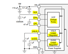
Regulators
|
VCP Charge Pump Reg |
Provides a higher voltage for the high side gate driver using capacitors and a switching circuit. |
VCP – stored charge pump voltage output VDRAIN or VM – charge pump voltage reference |
|
VGLS Linear Reg |
Provides an ~11V voltage source for the low-side gate driver voltage. |
Max input voltage Power dissipation |
|
|
DVDD Linear Reg |
Provides a 5V voltage source that is available for use by external circuitry. |
||
|
BUCK/BOOST Reg |
Provide a voltage source using a switching dc-dc circuit power regulator. |
Selection of external components such as capacitors, inductors, diodes, and switches |
|
|
Fault Detection
|
Over-current |
Circuit protection feature that triggers upon excessive current in the system. Often implemented by monitoring voltage drop across a series resistor. |
V_DS – MOSFET drain-to-source voltage V_Sense – voltage drop across R_sense |
|
Over-temperature |
Circuit protection feature that triggers a warning and fault upon excessive temperature in the system. |
Device temperature |
|
|
Under-voltage / |
Circuit protection feature that triggers upon irregular voltage. Various voltage supplies and regulators in the system may have this protection. |
VM - motor driver input voltage VCP – charge pump voltage VDRAIN – high side MOSFET drain voltage |
|
|
Gate Driver Fault |
Circuit protection feature that monitors gate drive voltage on GHx/GLx pins vs external MOSFET gate voltage. |
I_Drive – gate drive current setting T_Drive – gate drive timing setting MOSFET gate-source voltage (potential short) |
|
|
Output Switching |
Gate-Drivers and output MOSFETs |
Drive device outputs High/Low depending on device inputs. Requires proper gate drive voltage and gate drive current settings for optimal performance. |
Gate-drive voltage and current Output MOSFET ratings Device-specific truth-table logic |
|
Sensors and Feedback |
Hall-effect sensors |
Provide feedback on rotor position based on magnetic field of rotor. |
Motor driver system wiring/routing of signals |
|
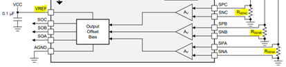
CSA - Current Sense Amplifier |
Monitor current flowing though LS of a half-bridge. - Closed-loop phase current feedback - implement external torque control |
R_sense - resistor selection Gain setting of CSA Unidirectional vs bidirectional current sensing |
|
|
Programmability |
I2C/SPI protocols |
Device may provide configurable functionality through the use of various memory registers and programmed user settings. |
Memory register addresses and bit values A device may also have storage registers for fault codes to indicate fault event type |
Elaborating the various device feature categories:
Power supplies
- VM is the main power supply of the motor driver IC, and is often biased at the voltage level of the motor.
- Under proper operating conditions, the supply voltage and current draw should be within datasheet limits.
- If this is not the case, then the device could be in an abnormal operating condition, or this could be a sign that the particular sample on your board has some damage.
Regulators
- The purpose of a regulator is to output a voltage in your system that has a consistent and specific value. There are many different regulator types such as Low-dropout linear regulators (LDOs), charge-pump regulators, and BUCK/BOOST regulators. You may want to check these features first, because these regulators are often essential to other circuits in your system such as gate drive voltage for HS and LS MOSFETs.
- If a regulator in your system does not have the correct voltage output, you will want to check if:
- It has been turned off by the device's protection features or a low-power/sleep mode feature
- The input voltages are all correct and connected to the device pins
- The gate drive current settings and waveforms of the gate drivers are behaving as expected
- An external passive component to your regulator input is missing or incorrect in value
- The device could be damaged internally, and the regulator cannot function because of it
Fault Detection
- A ‘fault’ is a detected event that indicates problems with a device’s current state of operation.
- The nFault pin and fault registers should be one of the first things to check if your motor is not working.
- There are many types of faults, but the main ones are based on voltage, current, and temperature. Many devices will include some sort of fault-detection feature to protect the system if a fault is detected, and will shut down device functionality to prevent further damage. To identify the specific fault type and what type of fault recovery mechanisms are present, please refer to the device datasheet.
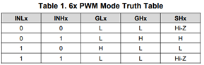
Output Switching
- A core function of your motor driver is the ability to control the gate drivers and toggle the MOSFETs on/off.
- The control logic will depend on your device’s control interface but is usually explained with a truth table to explain what outputs you will see for any given inputs.
- Note that the gate drive voltage and current are important to proper MOSFET operation.
- If your motor system has problems commutating, then one thing to revisit is the truth table logic. It may explain why your motor has trouble starting up or is spinning in the wrong direction, for example.
Sensored/Sensorless Feedback
- A feedback loop involving hall effect sensors or current sensing amplifiers is often used to detect motor position, to help the MCU drive the motor more efficiently.
- If your motor is not operating properly and your design includes these feedback features, a revisit of the datasheet guidelines can help identify problems with the CSA gain setting or input signals. Improper settings can also result in a false alarm for overcurrent fault detection at the output MOSFETs.
- Additionally, it is a good idea to check the system’s commutation algorithm and motor wiring.
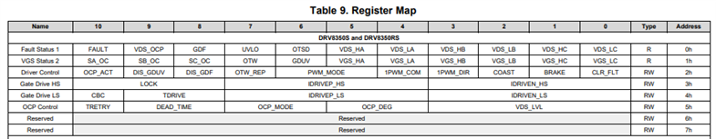
Programmability
- Some motor driver ICs may have memory (OTP/EEPROM) to configure settings for the motor.
- This requires a communication protocol such as SPI or I2C to read/write memory values in the chip and program the settings in place. The details of the settings and protocol used can be found in the specific device datasheet.
- Each feature configurable by memory will have a corresponding value in bit(s) at specific addresses, as outlined in the device register map. Unexpected device behavior could be due to using the wrong settings.
- As a best practice, check the datasheet to see what pull-up or pull-down resistors need to be present on your I2C pins (SCL, SDA) or SPI pins (SDI, SDO). Some other general guidelines on SPI are documented at the link below: