This thread has been locked.

If you have a related question, please click the "Ask a related question" button in the top right corner. The newly created question will be automatically linked to this question.

DRV8350S-EVM: question for DRV8350S

Part Number: DRV8350S-EVM
Other Parts Discussed in Thread: TIDA-01629

Hi Team,

After referring to TIDA-01629, the customer used this board to control the motor and found that the motor could not rotate. During the program debugging, it was found that the 6th bit of the No. 2 register of the DRV8350S chip is 1 (Indicates VCP charge pump and/or VGLS undervoltage fault condition). Is there a problem with the charge pump or VGLS?

Thanks,

Annie

  • Hi Annie,

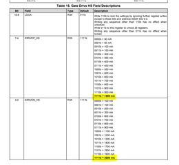
    Please consider lowering IDRIVE settings used in this application. The VCP or VGLS regulator is using too much average gate drive current and too much causes VCP or VGLS to dip in voltage over operation. 

    Can you share application specs, such as PWM frequency, motor current, motor voltage, IDRIVE settings, and whether sensored or sensorless trapezoidal commutation is used?

    Thanks,
    Aaron

  • Hi Aaron,

    This is the problem with the first board.The problem with the second board is that the fourth bit of the No. 1 register of the DRV8350S chip is found to be 1 during program debugging (Indicates VDS overcurrent fault on the A low-side MOSFET). May I know what is the reason?

    After the board is powered off, will the values written by the customer to the driver chip through SPI still be retained in the driver chip and read out at the next power on? For the first time, it is possible to use a small motor to open-loop and closed-loop. The default value in the driver chip he used. After changing the big motor, it will not work at all, it will not turn at all.

    Thanks,

    Annie

  • Hi Aaron,

    This is the problem with the first board.The problem with the second board is that the fourth bit of the No. 1 register of the DRV8350S chip is found to be 1 during program debugging (Indicates VDS overcurrent fault on the A low-side MOSFET). May I know what is the reason?

    After the board is powered off, will the values written by the customer to the driver chip through SPI still be retained in the driver chip and read out at the next power on? For the first time, it is possible to use a small motor to open-loop and closed-loop. The default value in the driver chip he used. After changing the big motor, it will not work at all, it will not turn at all.

    After the first board has a problem with charge pump or VGLS, measure the voltages at VCP and VGLS to be 50V and 3V. Then after replacing the new DRV8350S chip, the voltages are normally 58.5V and 14.5V, and can be rotated in open loop. Customer would like to know what causes the DRV8350S to be damaged?

    Thanks,

    Annie

  • Hi Annie,

    After the board is powered off, will the values written by the customer to the driver chip through SPI still be retained in the driver chip and read out at the next power on? For the first time, it is possible to use a small motor to open-loop and closed-loop. The default value in the driver chip he used. After changing the big motor, it will not work at all, it will not turn at all.

    When the chip is powered off, the SPI registers lose their content, and when powered back on, the registers reset back to their default values. It is likely when power was turned off and the new motor was replaced, the IDRIVE settings reverted back to 1A source/2A sink current. This likely caused damage at some of the pins, resulting in the GDUV fault. Replacing the chip will make the EVM work again if the lower IDRIVE settings are used. 

    After the first board has a problem with charge pump or VGLS, measure the voltages at VCP and VGLS to be 50V and 3V. Then after replacing the new DRV8350S chip, the voltages are normally 58.5V and 14.5V, and can be rotated in open loop. Customer would like to know what causes the DRV8350S to be damaged?

    The first board likely has damage at VCP and/or VGLS pins, because VGLS is normal to be 10-15V and VCP is expected to be VDRAIN + 10V. 

  • Hi Aaron,

    Thanks for your answer. 

    Last night, the board can drive a large motor to rotate in an open loop state. The current is about 0.6A without load (it seems that the current is quite large). Then power off and then power on again, the big motor can't turn. Check in the program and find that it is a problem with VGS_LC. The measured UVW-to-ground voltage is 0V, which is abnormal (24V during normal rotation). What are the reasons for the damage of DRV8350S, no protection at all?

    Thanks,

    Annie 

  • Hi Annie,

     Then power off and then power on again, the big motor can't turn.

    When powered off and back on, does the customer re-write their SPI settings? If not, default registers are used which are max IDRIVE settings. This can cause damage to device due to ringing, overshoot, undershoot, or coupling into LS gate. When powering a good device on, please set IDRIVE settings to low settings (i.e. 150mA/300mA source and sink current). 

    When powered back on, is nFAULT low before the damage occurred? 

    Thanks,
    Aaron