This thread has been locked.

If you have a related question, please click the "Ask a related question" button in the top right corner. The newly created question will be automatically linked to this question.

DRV8316: Cannot change output slew rate of DRV8316 using SPI

Part Number: DRV8316

Hi there,

I have an issue changing the slew rate and dead time of the DRV8316 SPI variant. 

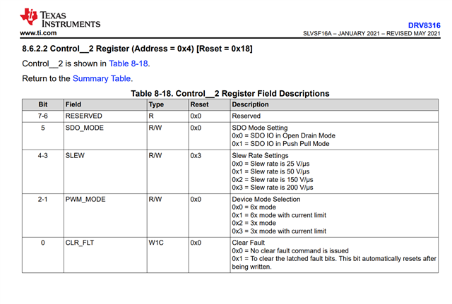
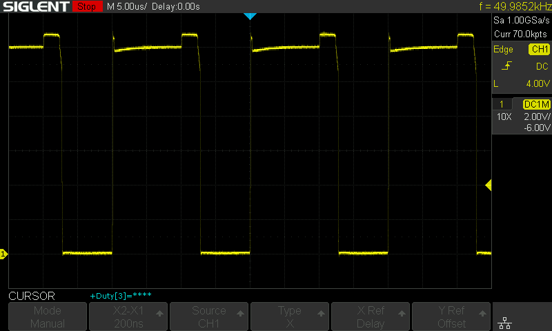
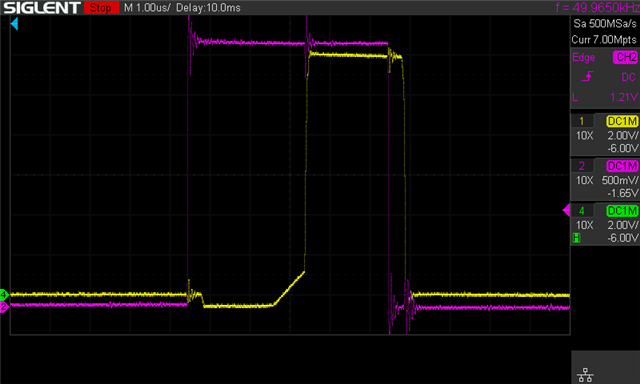
When probing the output of the DRV8316 using an oscilloscope, the duty cycle is distorted due to too much dead time being inserted. The dead time seems to be around 2.5us, which matches the dead time for slew rate of 25v/us. However, I have set the slew rate to 200v/us using SPI. Delay compensation is not enabled and I am using 3x PWM.

Here is the code that is used to writes the registers on the DRV8316. The registers should have been written successfully as the device is using 3xPWM correctly.

// format (r=1,w=0),(register 6bit),(even parity),(register data 8bit)
// 0,000011,1,00010011
drv8316communicate(1811, spi_buf);
// 0,000100,0,00011100
drv8316communicate(2076, spi_buf);
// 0,000101,1,00000001
drv8316communicate(2817, spi_buf);
// 0,000110,1,00010001
drv8316communicate(3089, spi_buf);
// 0,000111,0,00000001
drv8316communicate(3585, spi_buf);
// all other registers are left untouched

Trying to write other slew rates to the register results in the same behaviour.

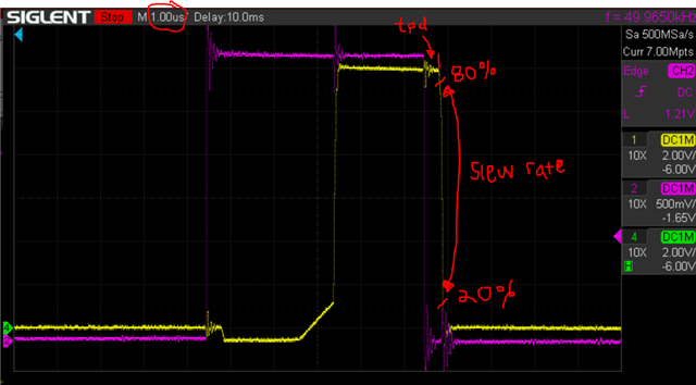
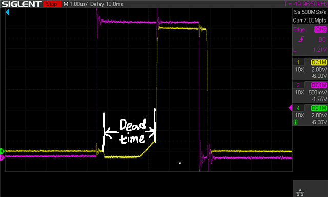
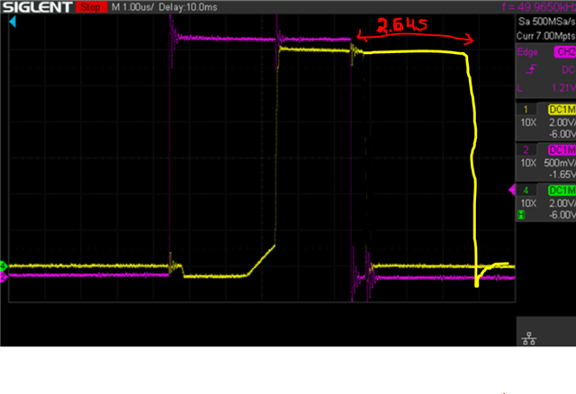
Here is an oscilloscope screenshot showing the input (purple) and driver output (yellow) for 1 channel. Notice the time from the output going below 0v to the time it goes to supply voltage is 2.5us.
In case this is an issue with the preproduction batch of chips, the lot number on the esd bag label is 1159778wdp and the markings on the chips are PDRV 8316X1 TI 148 AH2E G4.

Can someone please provide an explanation of why the dead time is longer than it is meant to be?

Thanks!

  • Hi Andrew,

    Some basic questions first to clarify the application:

    1) Have you tested that SPI writes and reads are working correctly? i.e. if you write a register and read it back, you get back the data you wrote into that register? Ensure clock polarity and clock phase is set correctly in the SPI initialization. We have an E2E FAQ on SPI configuration and use, and we even have an example with SPI using a C2000 MCU: e2e.ti.com/.../faq-spi-configuration-and-use

    2) What type of commutation are you using, trapezoidal or sinusoidal control? The current direction can affect dead time measurements due to the DRV8316's state machine to switch the integrated MOSFETs. This app note explains more: https://www.ti.com/lit/pdf/slvaf84

    3) Does this happen with the motor unconnected as well, or only when the motor is spinning?

    Thanks,
    Aaron

  • Hi Aaron,

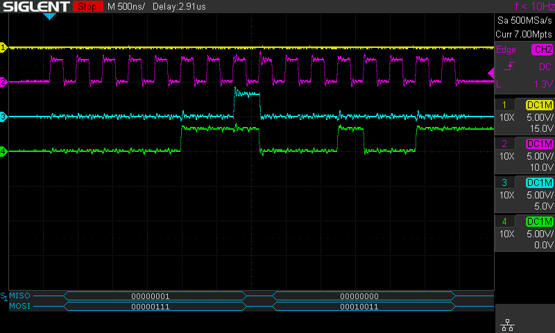
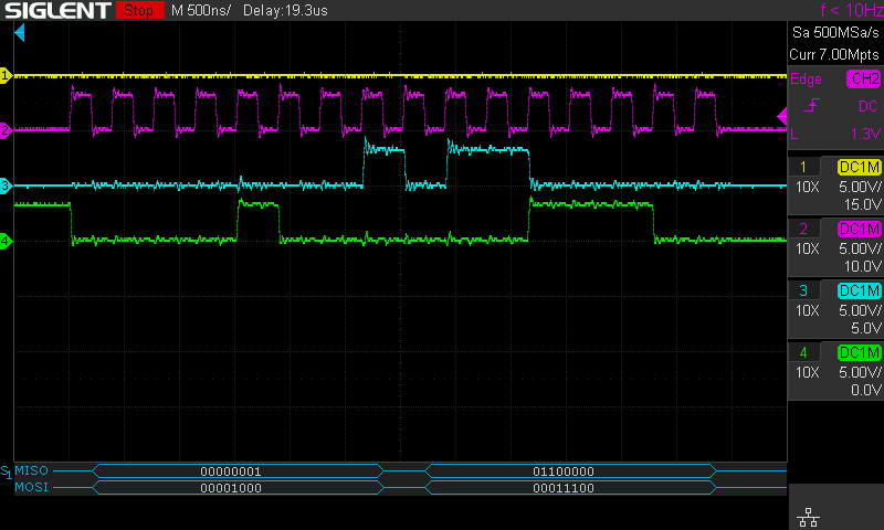
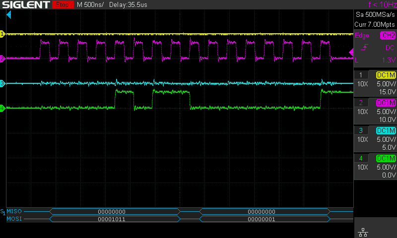
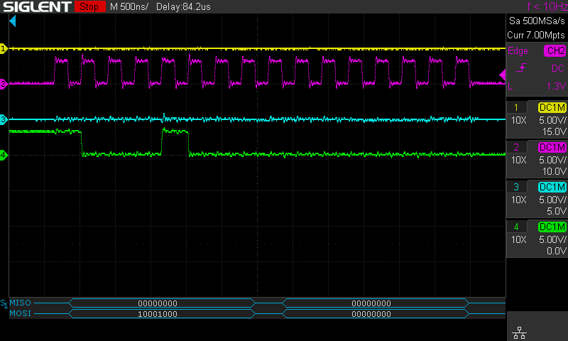
    SPI writes should be working correctly, as I am able to change the device from 6xPWM (default) to 3xPWM mode. However, I am having some issues with SPI reads not returning expected values. Also after the first few commands, the DRV8316 returns nothing. See oscilloscope screenshots.

    nSCS yellow, SCLK purple, SDO cyan, SDI green

    First SPI command after power on: unlock registers, expected return value 00010001

    Second SPI command: Set 3xPWM and slew rate to 200v/us, expected return value 00011000

    Third SPI command: Enable overtemp warning report, expected return value 00000000, from this point onwards SDO always stays low and returns zero for every command.

    Then the rest of the commands are sent. No response is received from the driver. The CSA gain register is set to 0.3v/a, which has been tested and is working as expected. This suggests that register writes are succeeding but reads are failing.

    After all registers are set, SPI register read back for the slew rate register is attempted, but it returns nothing.

    For the commutation type, I am using FOC, but there are some unrelated issues with the brushless motor's sensor, so for these tests a brushed motor has been connected to one of the phases. Current is flowing out of the phase. A 50khz PWM with constant duty cycle is being applied by the microcontroller.

    With no load on the output, the issue still occurs. But with no load the dead time reduces slightly to 2.4us.

    I hope you can give me some furhter insight into the cause of these issues.

    Thanks!

  • Hi Andrew,

    It looks like primarily we are dealing with an issue of SPI communication here, I will look at the waveforms in more detail and provide a response hopefully tomorrow.

    Regards,

    Anthony Lodi

  • Hi Andrew,

    I apologize for not getting back to you on this today, I will try to send a response later tonight.

    Regards,

    Anthony Lodi

  • Hi Andrew,

    After taking a closer look at the SPI waveforms, the reason why the SDO pin always 0 after the first 2 commands is because when you write 00011100 to register 4 to change the PWM and slew rate settings, you are writing a 0 to bit 5 (SDO_MODE) of register 4, which then configures the SDO pin in open drain mode instead of push/pull mode (thus requiring an external pullup to pull SDO high). To correct this, ensure that you always have bit 5 of your SPI write set to 1 when writing to register 4 to keep the SDO mode as push/pull mode. 

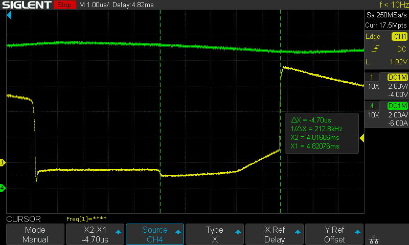
    Regarding the slew rate, the default slew rate is already set to 200V/us. Analyzing the waveform you provided, and noting the time scale of 1us per division, you will notice there is some propagation delay between the input command to slew the output low and the execution of that command. This propagation delay expected, you can reference the tpd specification in the datasheet. For 200V/us, based on the datasheet specs the average propagation delay is around 700ns. Based on your waveform, it looks like the tpd time of the waveform is around 400ns. For the slew rate, this is calculated in the region between 20% and 80% of the falling output voltage. This indicates approximately how fast the phase output voltage will fall in the region where the output is between 80% and 20% of the initial value. Looking at the waveform you provided, it seems like the slew rate correctly corresponds with a 200V/us slew rate.

    Hope that helps!

    Regards,

    Anthony Lodi

  • Hi Anthony,

    Thanks for pointing out the SPI issue. However, the dead time of the output still doesn't correspond with the dead time for the 200v/us slew rate specified in the datasheet. What is the cause of this?

    Regards,

    Andrew

  • Hi Anthony,

    Also regarding the bit 5 of CONTROL_2 register (register 4) the datasheet says that the value of reset is 0, so I was writing a 0 to it because the bit didn't need to be modified. It appears that SPI is in push pull mode after reset, as I don't have a pullup resistor on the SDO pin. Please fix this error in the datasheet.

    Regards,

    Andrew

  • Hi Andrew, 

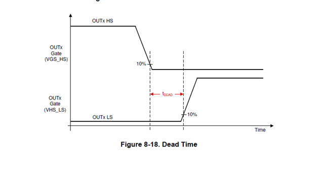
    Dead time is calculated from the start of the internal high side MOSFET being 10% on to the time when the low side MOSFET is 10% on (for OUTx going low). Since the device is integrated MOSFET, we are only able to monitor the OUTx voltage instead of the FETs individually. 

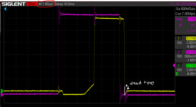
    There is one indicator that can be used to tell the deadtime (the time when both high and low MOSFETs are off): when the high side FET is switching off (assuming current has been flowing from the high side MOSFET to the phase), the current can no longer flow through the high side MOSFET so it will change to flow through the low side MOSFET body diode. This will be evident with about a -0.7V dip on the phase output voltage (this comes from the voltage drop across the body diode). Once the low side MOSFET turns on, then the current can flow through the MOSFET instead of through the body diode, so the -0.7V dip disappears. Therefore, the deadtime can be approximately determined by looking at the length of time that the body diode is conducting (indicated by the -0.7V drop). In the waveform you provided below, although the purple waveform obscures the yellow waveform due to some ringing on the purple signal that occurs at the same time, it looks like once the phase output signal switches off, there is a negative dip for a period (body diode conducting) before the output settles out at 0V. I have indicated in white the region that I am talking about, also indicating in white what I think the OUTx signal is doing in the region where the purple waveform is obscuring the yellow waveform. Considering the scale is set to 1us, it looks like from this waveform the deadtime is only a couple hundred nanoseconds in this instance.

  • Hi Anthony,

    I can see that the Dead-time from HS FET-off to LS FET-on is within the expected range. However the Dead-time from LS FET-off to HS FET-on is still very long (around 2.5us). I have fixed the SPI communications and can confirm that the registers read back what was written.

    Any explanation for this?

    Regards,

    Andrew

  • Hi Andrew,

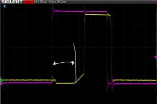
    Now I understand your issue. Can you verify that the INLx pin is high during the duration indicated by the white arrow in the image below? For 3x mode, If the INLx pin for this phase is low, then the output will be in hi-Z, regardless of the state of INHx.

    Regards,

    Anthony Lodi

  • Hi Anthony,

    INLx pins are tied to 3.3v by the microcontroller at boot and are never touched. I have verified that they are high during this time.

    Regards,

    Andrew

  • Hi Andrew,

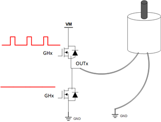
    Thanks for checking, you mentioned that you are using a brushed motor during the test. Are you connecting the brushed motor between one of the phases and ground as shown below?

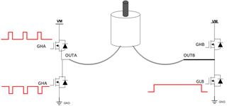
    Or are you connecting it between one phase and a second phase as shown below?

    Would you be able to provide a waveform of INHx and OUTx with an increased duty cycle to see if the deadtime increases? The reason I want to check this is because from the waveform you provided it seems that the time that OUTx is high is about half the time of the high pulse from the INHx input. I want to see if this will change if a longer duty cycle is used. 

    Regards,

    Anthony Lodi

  • Hi Anthony,

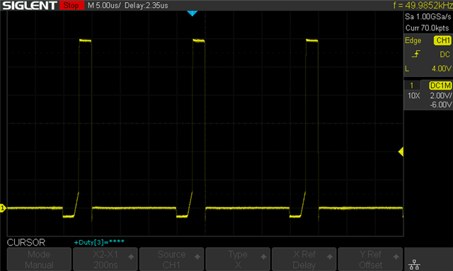
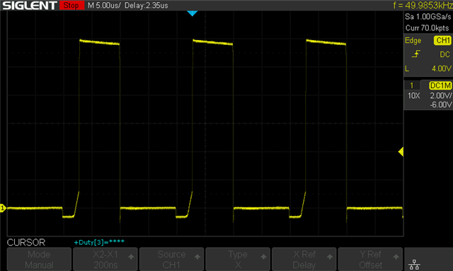
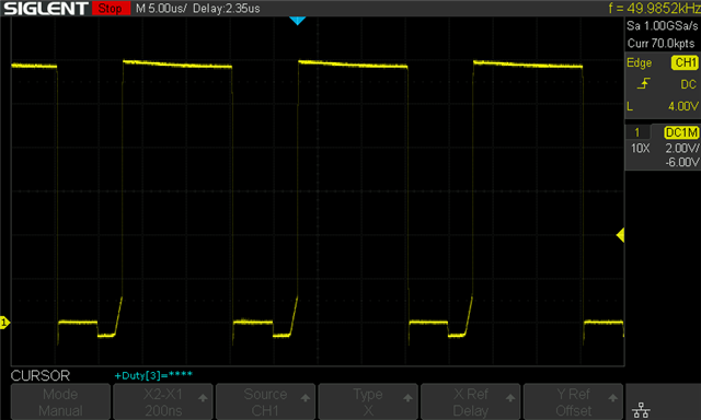
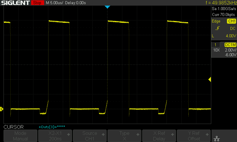
    For testing the brushed motor was connected between 2 phases, but connecting it between a phase and GND makes no difference. I've attached screenshots showing 25%, 50%, 75% duty cycles from the MCU. I've also done tests with 50% duty cycle with the brushed motor connected to GND, and where the phase is sinking current. PWM frequency is fixed at 50khz. It's a bit tricky to measure the output of the MCU as the signal is not exposed, so I've left out the PWM signal from the MCU.

    25% PWM duty cycle

    25% PWM duty cycle

    50% PWM duty cycle

    50% PWM duty cycle

    75% PWM duty cycle

    75% PWM duty cycle

    50%, other end connected to GND

    50%, other end connected to GND

    50%, phase sinking current

    50%, phase sinking current

    Regards,

    Andrew

  • Hi Andrew,

    Thanks for the additional data! It looks like it is not related to the duty cycle then, and the long deadtime depends on the direction of the flow of current. I'll discuss this issue in more detail with a coworker and I plan on following up on this with you Wednesday. Have you tried multiple boards/DRV8316 ICs and found the same behavior? Have you been able to run a brushless motor yet, and if so is the deadtime different than with the brushed motor?


    Regards,

    Anthony Lodi

  • Hi Anthony,

    I have tried 2 boards with DRV8316 ics so far, and they all have the same dead time issue. The ics are all from the same batch, so it could be a problem with this batch of ics.  I'll assemble a few more PCBs to see whether this is a board issue or not. Unfortunately, I don't have an evaluation kit to test this with.

    I have been able to run a brushless motor, but there are some unrelated issues with the sensor interacting with the control software. I'll run it sensorless for this test. I'll try to do the dead time test with the brushless motor today.

    Regards,

    Andrew

  • Hi Andrew, 

    Thanks for the reply, will wait to hear about the results of using a brushless motor to see if that makes a difference.  

    Regards,

    Anthony Lodi

  • Hi Anthony,

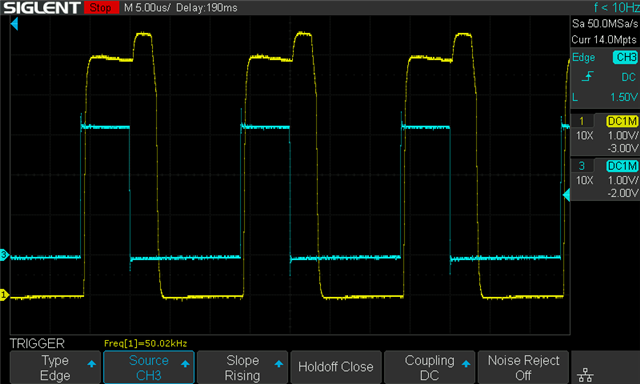
    I've made some measurements with a brushless motor, and the dead time is still around 2.5us. Since there are a few issues with the control software, it sometimes causes the brushless motor to fail to start up and get stuck. During this time I measured approximately 11 amps through the phase output before overcurrent protection activated, and the dead time was even longer at around 4.7 us. The wiring is not rated for 11 amps, which explains the large voltage drop in the output.

    So it seems that the dead time depends on how much current is flowing as well.

    Regards,

    Andrew

  • Brushless Motor Test Results

    Cyan: PWM input, Yellow: driver output.

    Current flowing out of phase

    Current flowing into phase

    Current changing direction (almost no current flowing)

    Interestingly, in this scenario there is almost no dead time, but with nothing connected to the phase the dead time is still present. Unfortunately, I can't measure the phase current as my current clamp doesn't measure accurately below 1 amp.

  • Hi Andrew,

    I appreciate this data!. it seems that the driver waits for the current in the phase to completely decay through the body diode before turning on the MOSFET. I intend to discuss this with a coworker today to try to figure out possible causes.

    Regards,

    Anthony Lodi

  • Hi Andrew, 

    I discussed this issue with a coworker, it seems like this isn't the first time this behavior has been observed on the DRV8316. I will reach out to others on the team to see if I can understand this behavior more and to look into documenting this in the future. In order to help the OUTx duration match the INHx duration, you can add delay compensation to compensate for the longer deadtime. While this will not remove the longer deadtime, it will offset the output to help align the input duration with the output duration. So if you are seeing 2.5us deadtime, then adding 2.4 or 2.6us delay compensation will help the output duration match the input duration. As illustrated in the image below, the additional delay will delay the output falling (for current flowing out of the phase) by the delay compensation time which will allow the overall output time duration to align closer to the duration of the on time of the input. 

    It seems like this behavior that you are seeing is related to the amount of current flowing through the phase and the inductance of the motor. It seems that the best solution is using the delay compensation feature.

    Regards,

    Anthony Lodi

  • Hi Anthony,

    Adding the delay compensation does help to fix the dead time, but unfortunately the current cannot be measured accurately during the dead time of the MOSFET. This means operating at high duty cycles isn't possible if current measurement is needed. I understand that replacing the ICs is required to fix this problem. 

    Will the production version of the DRV8316 fix this issue? Or is this intended behaviour and the datasheet is incorrect?

    Does the DRV8316-Q1 also have this issue? It is in production and the datasheet specifies a dead time typical of 500ns at 200v/us slew rate. Is it pin-to-pin compatible with the DRV8316?

    Regards,

    Andrew

  • Hi Andrew,

    This behavior is newly discovered so unfortunately I don't have all the answers to your questions yet. I am working with the team to fully understand this and to see if the datasheet needs to be updated or if there is a different solution.

    I am not sure whether or not the issue has been observed/reported on the DRV8316-Q1, so I don't know if it will perform differently than the DRV8316 on this particular behavior. The DRV8316 and the DRV8316-Q1 are pin to pin compatible, but as of right now we are out of stock on the DRV8316-Q1 on TI.com.

    I will keep you updated as to whether or not this behavior is something that will be changed in the future or if the datasheet will be updated.

    I agree with your analysis that this does produce a limitation on the ability to sense current for that particular phase if the duty cycle is too high. You would only be able to sense current in the phases which have the low side FET on for a sufficient duration of time to measure the current. 

    Regards,

    Anthony Lodi 

  • Any updates on this?

  • Hi Andrew,

    I tried to replicate the issue in lab, but was unable to do so while running a motor at close to 2A peak current. The deadtime I was seeing was around 500ns. I wasn't able to operate higher than 2A because of motor limitations. What is the inductance of the motor that you are using? It could be that it is necessary to use a high inductance motor to replicate the issue. Could you try operating your motor at 2A peak current and seeing if you still see the deadtime issue?

    Regards,

    Anthony 

  • Hi Anthony,

    Since I suspect that the issue is related to the batch of chips, which batch were you using to replicate the issue? Was it an eval module? I am using ICs on a custom PCB. The lot number on the esd bag label containing the chips is 1159778wdp and the markings on the chips are PDRV 8316X1 TI 148 AH2E G4.

    The rated inductance of the brushless motor is 64 uh. (and in case it's relevant, the resistance is 461 milliohms) Unfortunately I'm not able to measure the current accurately when running a brushless motor due to my current clamp not having enough bandwidth. When running a brushed motor for testing the issue occurs at every current level. Unfortunately I don't have the datasheet for the brushed motor.

    Regards,

    Andrew

  • Hi Andrew,

    Thanks for the additional information! We plan on performing additional testing today, I will keep you updated.

    Regards,

    Anthony Lodi

  • Hi Andrew, 

    With some help from my coworkers we were finally able to replicate the issue in lab. The issue is that the reserved bit 6 of the Control_3 register should default to 0x1, not 0x0. If this reserved bit is set to 0x0, this will cause the behavior that you are seeing. The DRV8316-Q1 datasheet shows the correct default value, and we will update the DRV8316 datasheet accordingly. Ensuring that 0x1 is written to this reserved bit should resolve your issue.

    Thank you for your patience and I apologize for the inconvenience!

    Regards,

    Anthony Lodi

  • Hi Anthony,

    Changing the reserved bit resolves the long dead time issue, the dead time is now around 500ns. Thanks for the help!

    Regards,

    Andrew

  • Hi Andrew,

    Glad to hear that resolved your issue! 

    Regards,

    Anthony Lodi