This thread has been locked.

If you have a related question, please click the "Ask a related question" button in the top right corner. The newly created question will be automatically linked to this question.

DRV8307EVM: is this shoot throw or is this incorrect controls?

Part Number: DRV8307EVM
Other Parts Discussed in Thread: DRV8307


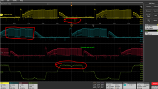
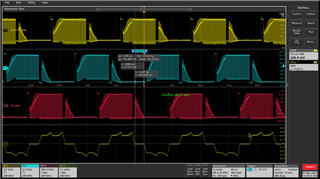
This is our Main Board running a DRV8307….. Below is yellow, blue, red are the three phases (line to return) and the green is one phase current.


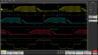
This is TI’s EVM Board running a  DRV8307….. Below is yellow, blue, red are the three phases (line to return) and the green is one phase current.


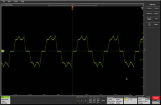
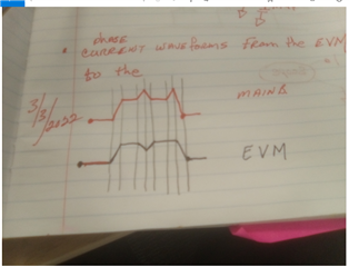
Now: I hand drew the green current waveforms below and is my question; I drew the conducting part of the current waveforms from above; one from the main board and one from the TI EVM board.

The Main board has two peaks with a slope up and a slope down, the TI EVM board has one peak and starts a slope down and then a slope up….. is this shoot throw or is this incorrect controls?


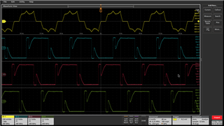
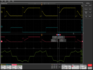
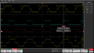
A clearer screen capture: yellow= phase voltage, blue=low side gate of fet, red=highside gate of fet, green is the phase current…..   THE OTHER PHASES LOOK TO BE CURRENT LIMITING

BECAUSE THE HIGHSIDE GATEDRIVE VOLTAGE IS LOWER THAN THIS ONE ( 24 +10) , THIS ONE IS AT 34 VOLTS THE OTHER TWO ARE NOT…..

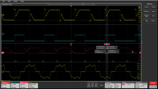
Screen shot of next phase lowside and highside gate voltages; high side is being voltage limited:

and the third phase;

emails:

Calvo, Matthew <m-calvo@ti.com>

McKay, Scott <Scott.Mckay@irco.com>

  • Hi Scott,

    You can see that your board is actually spinning the motor much better than the EVM actually. On the EVM, there are many issues:

    - Negative voltage spikes on U, V, and W
    - Cut off duty cycle outputs on U, V, and W (cycle by cycle current limiting looks to be the root cause)
    - Torque ripple on the current output

    Looking at the EVM, either shoot-through currents are happening or the ISEN resistor is too small. The EVM's ISEN resistor = 50mohm, which means any current above 0.25V/0.05 = 5-A will exceed the VLIMITER spec and cause a cycle-by-cycle current limit. Cycle-by-cycle causes the UHSG, VHSG, and WHSG outputs to turn off until the next PWM input, causing smaller PWM output duty cycles and a large current ripple. 

    What is the peak voltage and current in this application, and what value of ISEN do you all use?

    Thanks,
    Aaron

  •  

    I will try to post this but I would like to get this out a fast as I can …..  I changed the current sense resistor and took this screenshot above :

      The current increased and the hz (frequency) was good but only pumped 2.5 gals/minute compared to the EVM that pump 6 gals/minute ……  The current increase must be all shoot-through.

    Current waveform looks great but does not produce anything more than the lower current limit.  Did not change the gals/minute.

  • This issue has not been resolved...

  • Hi Scott,

    I see your attached waveform of current, but it is in volts and I have no idea what level of current is in the waveform since you did not share your ISEN resistor value. This waveform of current looks good and does not look like it is being limited whatsoever or else you would see ripples in the motor current waveform and average lower peak currents. 

    If you are not getting enough power from your application, can you ensure that you are measuring the same current performance from the motor with your PCB as you were with the EVM? Are there any differences between PCB and EVM? Can you share schematic? 

    On the PCB, can you share a waveform of the Hall sensors to make sure that they have six 60 degree electrical phases? If there is any difference due to Hall sensor misalignment or bad Hall signals on the PCB then you can see worse commutation. Can you also confirm on the U,V, and W phases on the PCB that the waveforms look good?

    I would also ensure that the high-side gate voltages go to VM+VCP (in your application ~34V) when they switch on, and that VCP is measured to be 34V with respect to GND. 

    Low side gate voltages will go to 10V when switched on, so make sure those voltages are correct. 

    Thanks,
    Aaron

  • Thanks Aaron.... did not have time to update information .... but will...  I follow every thing you wrote...  Will get the appropriate screen shots.... And I need to look at all these waveform again anyway..... 

  • Hi Scott,

    No worries, please keep me posted when you have screenshots available to help further debug. 

    Thanks,
    Aaron

  • Cleaned things up …. Yellow is one of the phase currents (X100 proble) blue, red, and green are the phase voltages…  Not all the waveforms are here.  Made a couple of mode to my circuitry and the last one was “change of direction” the pump is now pumping 7.5 gallon per minute….. Thank you for you review and support……