Other Parts Discussed in Thread: DRV8251A
Hello, 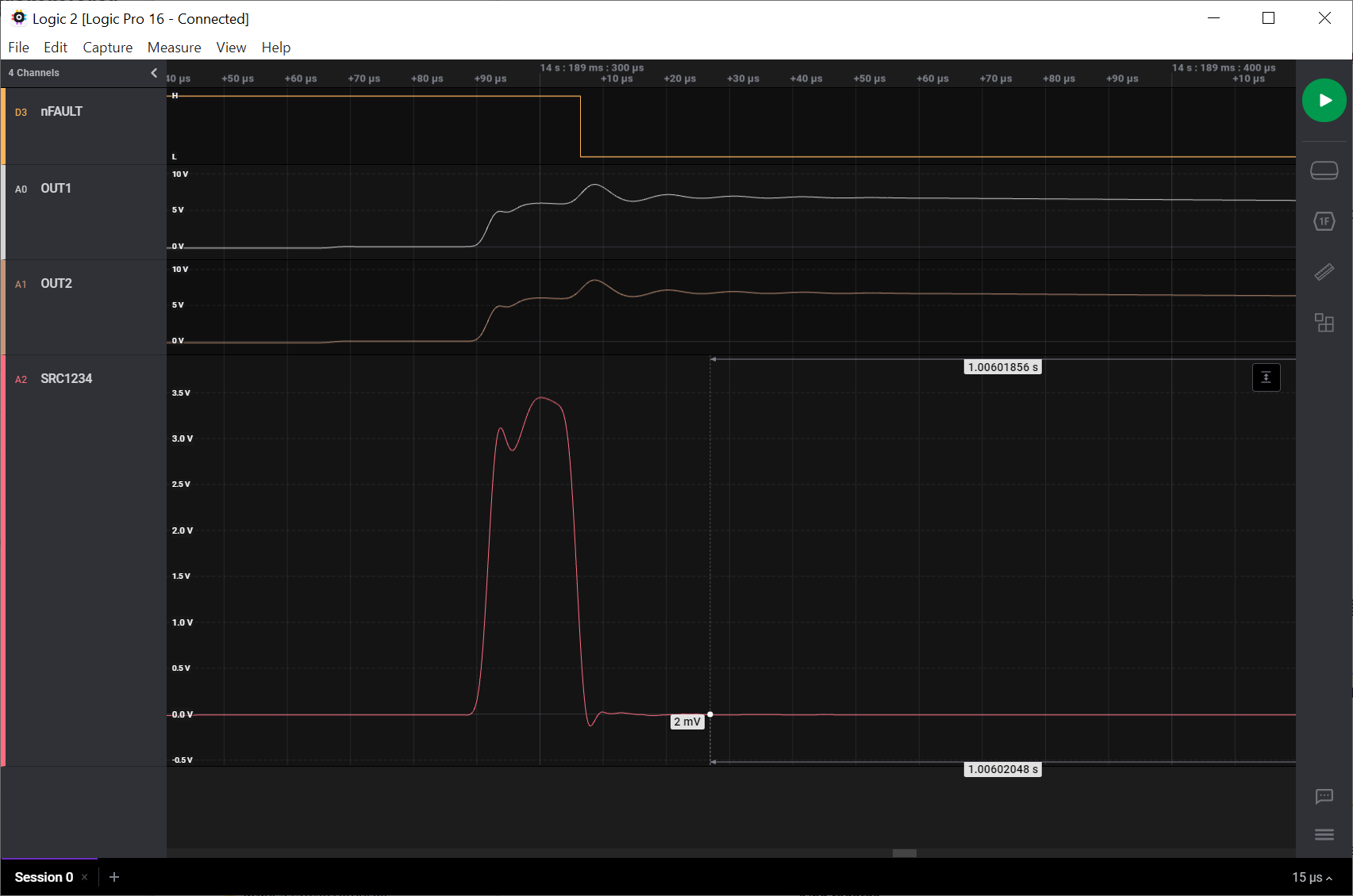
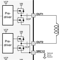
I am designing a control board for bistable water valves operated at ~9V. I'd like to control the on/off solenoid current bursts (300mA for 250ms resp. -50mA for 60ms) and to detect various abnormal conditions including valve presence and shorted terminals. To simplify the design I was planning to use a 1R shunt resistor and to deliver the SRC12/34 voltage (via 1k) to the ADC input of the uC (which offers a VREF of 1.1V and allows a max voltage of 5V).
Now, shorting the terminals I observe that the voltage at SRC12/34 rises to 3.5V for 15us and that then the overcurrent protection of the DRV8844 kicks in, shutting down the FETs.
But according to the datasheet the max voltage at SRC12/34 is +-0.6V. This datasheet max voltage requires me to use a much smaller shunt resistor e.g. 0R1, and therefore limits my ability monitor with the uC the inductive current rise (in order to detect the solenoid presence) in this simple way. Rather I would probably have to add some OPA amplification of the SRC12/34 signal on the board, adding quite a bit of noise.
Now, I was assuming that the max +-0.6V versus VNEG indicates that the FET source is protected from ESD by some clamping diodes. But according to my measurements the voltage *does* rise to 3.5V at SRC12/34 when shorting the terminals. How can that be?
So my question basically boils down to: What happens if I exceed the 0.6V on SRC12/34? Which components in the IC are stressed by this voltage and how much? And would it be OK if this happens only rarely and shortly?
Kind regards,
Sebastian