Hello team,
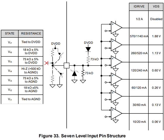
Where is approximately the threshold which switch the IDRIVE setting?
Customer is concerned about the situation that the resistor becomes out of 5% due to the temp drift etc...

Thank you.
Regards,
Hirata
This thread has been locked.
If you have a related question, please click the "Ask a related question" button in the top right corner. The newly created question will be automatically linked to this question.
Hello team,
Where is approximately the threshold which switch the IDRIVE setting?
Customer is concerned about the situation that the resistor becomes out of 5% due to the temp drift etc...

Thank you.
Regards,
Hirata
Hi Hirata-san,
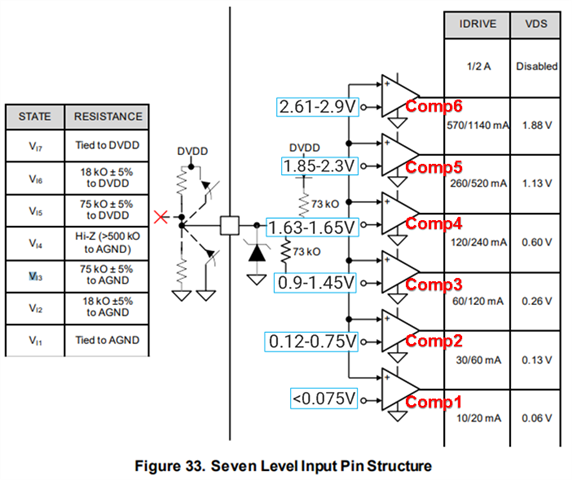
The way the 7-level input works is that when a resistor is set, the input voltage (VIx, where x = 1-7) is set due to the resistor divider internally from DVDD. Depending on that input voltage, it will trip internal comparators high if that voltage is over the comparators threshold voltage. For instance, VI3 is valid if it trips comparators 1-2, or VI7 is valid if it trips comparators 1-6.
Here are the thresholds to guarantee each setting:
VI1: 0V
VI2: 0.12-0.75V
VI3: 0.9-1.45V
VI4: 1.63-1.65V
VI5: 1.85-2.3V
VI6: 2.61-2.9V
VI7: 3.3V
Thanks,
Aaron
Hi Aaron-san,
This is what I request so thank you for your answer. but I would like to know a bit more detail.
If my understanding correct, I think below image is what you are saying.

For instance, VI3 is valid if it trips comparators 1-2
If we put 75kOhm resistor to set the VI3, the input voltage should be 1.11V.
If the threshold of VI3 is from 0.9V to 1.45V, comparator 1 and 2 will be tripped, but comparator 3 might be tripped but might not be tripped.
It means if we place 75kOhm it can be recognized as VI3 and VI4 dependent on the situation?
How to think?
I attached my calculation below.
VI7: 3.3V-3.4V
Also How to think VI7? There is 6 comparator according to your explanation.
Thank you.
Regards,
Hirata
Hi Harata-san,
The voltages I shared are not the comparator threshold values, but rather the voltages that guarantee the logic settings above. I do not want to share all internal comparator threshold values as this is internal design data.
The voltages I shared before are the guaranteed voltages in which the previous comparators trip because there is a min/max value for the thresholds. If you had a voltage like 0.8V at the pin, then we don't know if Comp2 will trip, so we cannot guarantee whether the setting will be VI2 or VI3 in the in-between cases.
If we put 75kOhm resistor to set the VI3, the input voltage should be 1.11V.
Yes, so 1.11V means it will be VI3 because 1.11V will exceed the comparator voltages for Comp 1 and Comp 2.
These comparators are not the input voltage settings, because there are only 6 comparators and 7 possible levels. The states of the comparators determine the VIx setting in internal logic. The logic is below:
VI1 --> no comparators trip
VI2 --> Comp 1 trips
VI3 --> Comp 1-2 trips
VI4 --> Comp 1-3 trips
VI5 --> Comp 1-4 trips
VI6 --> Comp 1-5 trips
VI7 --> all comparators trip
If 75k +/-5% = 71.25k to 78.75k, then the voltage range of the pin will be 1.09V to 1.13V. This is well within the guaranteed range for VI3, which will yield the appropriate seven-level input setting.
Therefore the datasheet's +/- percentage ratings are correctly specified so that these resistors will guarantee the hardware settings chosen.
Thanks,
Aaron
Hi Aaron-san,
Thanks for the clarification.
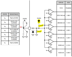
When we se the internal block diagram, there is diode at the DVDD, internal 73kOhm resistor for resistor divider, and internal ESD diode.
How to think about below?
1. the applied voltage is "DVDD - Vf"? or are we able to think the applied voltage is DVDD?
2. DVDD also have some variation. Are we able to think this is 3.3V? or we should think it as 3.0V to 3.6V?
3. How much tolerance 73kOhm? Are we able to assume ideal 73kOhm?
4. Are there any leak current of the ESD diode?

If we can calculate ideally (Vf=0V, DVDD=3.3V, 73kOhm with 0% tolerance, no leak at internal ESD diode), it is easy to calculate like below. How do you think?
To set VI1, Just tie to GND
To set VI2, Resistor can vary from approx. 3kOhm to 30kOhm
To set VI3, Resistor can vary from approx. 45kOhm to approx. 260kOhm.
To set VI4, Just leave open.
To set VI5, Resistor can vary from approx. 60kOhm to approx. 260kOhm.
To set VI6, Resistor can vary from approx. 12kOhm to approx. 26kOhm.
To set VI7, just tie to DVDD.
To answer customer question, I don't think exact value of the threshold, but want to know the rough picture where is the threshold to switch the VIx.
Do you think below is acceptable answer for customer?
"We recommend to keep the resistance within +/-5% but there is little possibility that VIx state changes even when resistance is a few % out of the recommended +/-5% tolerance range."
Regards,
Hirata
Hi Harata-san,
1. the applied voltage is "DVDD - Vf"? or are we able to think the applied voltage is DVDD?
I need to check if there is voltage drop across that diode, you can check in parallel using a diode test on a DMM from DVDD to IDRIVE.
2. DVDD also have some variation. Are we able to think this is 3.3V? or we should think it as 3.0V to 3.6V?
We assume 3.3V typical at room temp, but it can be anywhere from 3 to 3.6V across VM and temperature ranges.
3. How much tolerance 73kOhm? Are we able to assume ideal 73kOhm?
I assume ideal 73kohm. Since 7-level inputs are used in many BLDC devices, I assume the spec of +/-5% is based on comprehensive testing the factors you mentioned (internal design, DVDD variation). I would not recommend going beyond or suggesting anything higher than +/-5% resistor value if the customer's application has a large VM or temperature range.
4. Are there any leak current of the ESD diode?
The leakage current should be negligible as this is a standard ESD diode placed across many of our device.
The revised statement should be:
"We recommend to keep the resistance within +/-5% as we cannot guarantee the VIx state does not change when resistance is a few % out of the recommended +/-5% tolerance range."
Thanks,
Aaron