This thread has been locked.

If you have a related question, please click the "Ask a related question" button in the top right corner. The newly created question will be automatically linked to this question.

DRV8300DIPW-EVM: No gate PWM

Part Number: DRV8300DIPW-EVM
Other Parts Discussed in Thread: DRV8300

Hi,

I made a design with a DRV8300DI gate driver IC for a motor control application. The problem that occurs is,

that when I give a PWM signal to INHx/INLx combo, I get no output PWM signal for the gate and I'm unsure, what I'm doing wrong.

For the PWM generation I took a C2000 uC and the DRV8300DI receives the PWM signals fine. The supply voltage is 12V and looks also fine.

The BSTx voltage is around 5V, but this is probably because there is no PWM for bootstrapping. Also the DRV8300DI nFault pins stays high (pull up).

There is no motor attached, just the gate driver that receives the PWM signal and does not forward it to the MOSFETs.

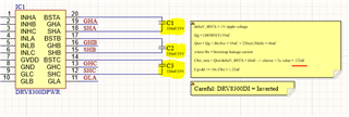
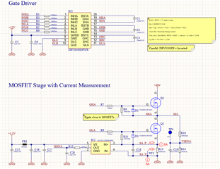
The schematic for the gate driver with one half bridge is depicted here:

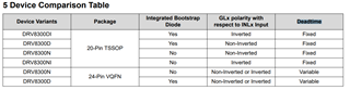
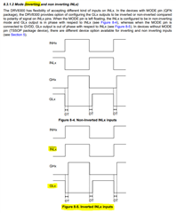
(Note: I used the DRV8300DI and not the DRV8300D)

(Note: There are 4x220uF bulk and a lot of ceramic directly at the MOSFETs)

Layout:

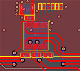
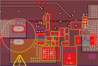
I'm currently out of ideas what I'm doing wrong.

Edit: One thing I see is, that when I let INLx to GND and just PWM on INHx, I get a PWM signal for GLx. So it seems, that the 2-Channel PWM from the C2000 does make some trouble with this controller.

Edit2: Might this be a problem with a undervoltage lockout? The voltage from BSTx to SHx is around 7V at startup (probably through the voltage dividers from GHx to SHx and there to the VSENSx measurement. BTW I use 50% PWM signals for INHx and INLx

  • Hi Sebastian,

    Can you replace the 100-ohm resistors with 0-ohm resistors from the C2000 IC? Can you ensure the PWM edges are defined well at the DRV8300 inputs? Are you sourcing 1 PWM to both INHx and INLx from the C2000 uC? Can you confirm if the uC can provide enough current to generate the PWM correctly?

    What PWM frequency is your 50% PWM signal?

    Could you try turning on the LS PWM first using INLx=GND and INHx=PWM before applying the PWM signal at the input? This will refresh the bootstrap caps first before applying the HS PWM signal. You might want to increase your bootstrap caps to 1uF if there is not enough bootstrap capacitance to turn on the HS FETs. 

    Thanks,
    Aaron

  • +Thanks Aaron! 

    Hi Sebastian, 

    A few other things I wanted to mention: 

    1. MODE pin affects inverted/non-inverted PWM inputs 
      1. I would advise checking what this is in your system and evaluating whether the behavior makes sense
      2. can also try out the different MODE pin settings to see if we get a different result for various INHx/INLx operating conditions  
    2. Bootstrap cap selection
      1. noticed that your bootstrap caps are actually relatively large at 220nF* (corrected units)
      2. I see that your calculations took Section 9.1.1 'bootstrap cap and GVDD cap selection' info into consideration 
      3. however, you may want to reduce the value to 122nF later on so that they charge up to proper bootstrap voltage more quickly 
        1. make sure caps are properly rated for 2x the expected voltage differential (pick 122nF value, but rate it at 25V or higher)
    3. Input signals at INHx, INLx
      1. like Aaron mentioned, it may be worthwhile trying to slow things down and manually apply INHx/INLx slowly at various combinations of High/Low states to see if output toggles
      2. I have a suspicion that your bootstrap voltage across BSTx caps are taking too long to power up under your application's PWM frequency being tested 
      3. so we can try to see if giving BSTx more time to charge up will work 

    MODE pin description: inverting/non-inverting 

    Best Regards, 
    Andrew 

  • Hi Aaron, thank you for your reply. The replacement of the 100Ohm resistor makes no difference. The PWM edges are well define and that should not be the issue. I'm sourcing 2 PWM signals, one for INHx and one for INLx (exactly what the Motor Control Library in the universal motor control lab does), where the signal have a small deadtime in between. The uC has enough current to generate the PWM correctly.

    The frequency is 20kHz.

    I will try what you recommended

  • Hi Andrew,

    Thank you for the suggestions

    1.) I use the DRV8300DI, there is no mode pin. It will make more sense to use the DRV8300D in the end, but it is a question of availability.

    2.) The bootstrap is at 220nF, not 220uF. The caps are rated for 25V, so degeneration should not be a problem, but I can try to reduce it later. One more thing I notice is, that when I apply the two PWM channels, the SHx Voltage goes to 5V, where the BSTx is at 11.4V, so this might be a bootstrap untervoltage. So should I increase to 1uF?

    3.) I will try to set the PWM frequency down to 1kHz for testing.

    Edit: 1kHz PWM does not change anything

    Edit2: One more thing: When I connect INLx to GND and give a PWM to INHx, I get the GLx PWM, but no GHx PWM

    Edit3: I also tested another board, but exactly the same behaviour

  • It works now, when I connect INHx and INLx to just 1 PWM channel from the C2000. I'm not completely happy with that, since I would like the possibility to for braking the motor as it can be done on other DRVxxx devices.

    One more question: When I use the inverted INH/Lx, do I need the INLx channel from the C2000 and for the normal mode, I only use the INHx channel?

  • Hi Sebastian, 

    Thanks for the updated response 

    Acknowledged on below details: 

    1. Correct that PW pkg device variant not having a MODE pin 
    2. Cap values- correct that units are nanoFarads as described. Having 25V rating or higher should be good to avoid de-rating. 
    3. Misc PWM debugging 
      1. acknowledged that the output GHx/GLx PWMs appear to work when INHx/INLx are toggling together
      2. I added some details below that will explain further 

    Some updated advice to help debug:

    • Two mechanisms to discuss:
      • dead-time (table below)
        • If your operation is supposed to toggle GHx=GLx=High at the same time, it will force something called 'dead time' to prevent both MOSFETs of the H-bridge from turning on at the same time. We don't want both ON simultaneously, because this will lead to shoot-through condition (low resistance path between 15V and 0V)
      • inverted PWM operation (diagram below)
        • according to 'inverted' variant operation (which matches your DRV8300DI device), toggling both INHx=INLx together would commutate GHx and GLx appropriately and automatically insert dead-time also. This is confirmed working from your results also. 
        • however, when you set INHx= PWM and seeing issues,
          • you are also permanently holding INLx=GND (Low), which the inverted logic translates to GLx=H 
          • this means GLx=H except when you also toggle GHx=H, in which the DRV IC triggers dead-time and shuts off LS FET with GLx=H, and then it recovers when INHx=L again. This is probably why you are seeing a 'PWM' on GLx even though you are not toggling INLx signal
        • to test out this theory, I think the right experiment would be to hold INLx=H always, so it keeps the LS FET OFF.
          • This would result in only HS driver output being operational, and you should see GLx=L while GHx=PWM 
    • might need to map out the circumstances to further analyze the info - see table below, and I think we've found root cause to be the commutation logic itself 
      INHx input INLx input GHx Behavior GLx Behavior
      PWM L/GND no activity 'PWM' 
      PWM PWM PWM  PWM 
      PWM H/3.3V TBD? expect PWM TBD? expect Low always
      L/GND PWM TBD? expect Low always TBD? expect PWM

    Best Regards, 
    Andrew