This thread has been locked.

If you have a related question, please click the "Ask a related question" button in the top right corner. The newly created question will be automatically linked to this question.

DRV8871-Q1: coil load and current sense

Part Number: DRV8871-Q1

Dear team,

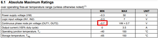
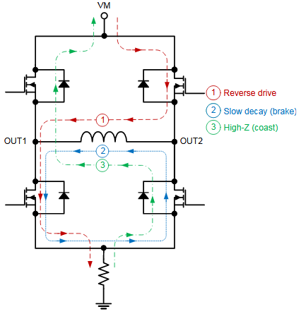
My customer wants to use our device to drive a coil, and there will be bidirectional current on this coil. In addition, this coil has a special feature, when the current flowing through the coil is less than 0.1A, its equivalent inductance is about 5H, and it will suddenly change to 0.5mH when it exceeds 0.1A.

1. Can our device drive such coil?

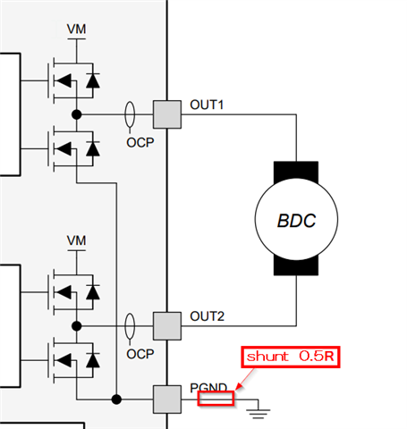
2. They want to place one shunt resistor(0.5ohm) between PGND and actual GND, this resistor is used to monitor the current, is it ok? In the second picture, I noticed there is one resistor connected to GND, it should be the shunt resistor, right?

Thanks & Best Regards,

Sherry

  • Hello Sherry,

    Thanks for checking with our team. I believe you want to size the current sense resistor so that minimum node pin voltage does not fall below -0.7 V. 

    So assuming the minimum output voltage (VOUTx) is 0 V, a 0.5 ohm current sense resistor would support up to 1.4 A output:

    0.7 V / 0.5 ohm = 1.4 A

    Let me know if that makes sense. Thanks!
    Tilden

    EDIT: We also need to account for voltage across the resistor, so the maximum voltage across OUTx to GND = -(Vdiode+Vsense). I'll provide an update with a better answer tomorrow.

  • Hi Tilden,

    Could you please help give me the reply? 

    Thanks & Best Regards,

    Sherry

  • Hello Sherry,

    1. I think so, but the customer needs to try and confirm.

    2. The 0.5 ohm shunt resistor should support up to 1.4 A output current. We want to keep the voltage across GND to PGND above -0.7 V to avoid current flowing back through the FET body diode. So 0.7 V / 0.5 ohm = 1.4 A. So sizing the shunt resistor will depend on the motor current.

    Let me know if that makes sense. Thanks!
    Tilden