A related question is a question created from another question. When the related question is created, it will be automatically linked to the original question.
If you have a related question, please click the "Ask a related question" button in the top right corner. The newly created question will be automatically linked to this question.
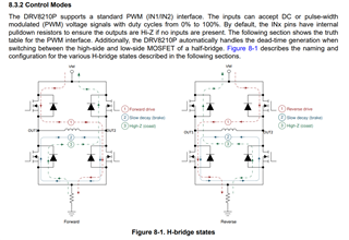
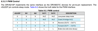
This device won't work for your application. This driver doesn't change the output voltage, it just controls the H-Bridge states as shown here:
When driving (Forward/Reverse drive) this will basically be a PWM signal at VM voltage.
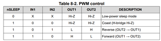
If you were controlling a motor, see Table 8-2 PWM Control in the datasheet. You should tie IN2 HIGH or low depending on if you're going to drive the motor forward or reverse. Though IN1 and IN2 do have a internal pulldown resistor (Table 6-1. Pin Functions), so if you leave them floating they will be in a high state.
Looks like this post was accidentally posted 3 times, I have deleted the other two instances of it.
Ahh I see. That should be possible. Since IN2 has a internal pulldown resistor, if you leave it disconnected then you'll be switching IN1 between HIGH and Hi-Z output. I suspect you would prefer switching between LOW and HIGH output, which you could achieve by tying IN1 HIGH and PWM IN2.
Since this is outside the typical use case for this chip, I highly suggest ordering a DRV8210EVM or request some samples of DRV8210P and testing it out before you get too far into your PCB design/ordering process. You can swap out the DRV8210 chip on that EVM with a DRV8210P, though note that pin 7 is MODE on 8210 vs nSLEEP on 8210P, so you'll need to externally control that.
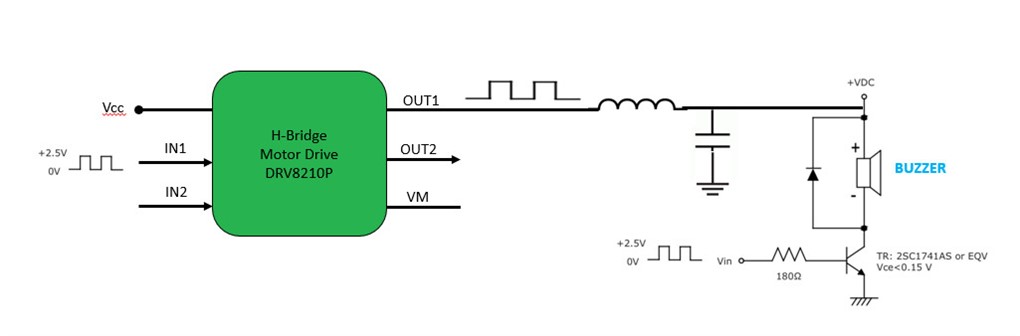
We would like to use a PWM signal in IN1 to control the output voltage level on OUT1.
May I know if the IN2 and OUT2 pins could be floating?
If IN2 is floating then internal it is pulled low, and according to the logic table, with IN1 driven by PWM input signal the OUT1 will be either VM or hi-Z, which won't work as input to the low-pass-filter, which needs to see a true PWM output switching between VM and GND.
So here I would do: connect an inverter input to IN1, then connect inverter output to IN2.