This thread has been locked.

If you have a related question, please click the "Ask a related question" button in the top right corner. The newly created question will be automatically linked to this question.

DRV8426: I'm looking for a way to reduce jitter performance in a stepper motor.

Part Number: DRV8426
Other Parts Discussed in Thread: , DRV8428

Dear Expert,

Hi, my name is Byeongsu, Kang, and i am in charge of electrical circuit and control for ACS module.

I'm looking for a way to reduce jitter performance such as audio noise or control error in a stepper motor. The motor specifications are as follow;

  • Nominal Voltage : 12 V
  • Resistance : 180 ohm
  • Inductance : 90 mH
  • Step Size : 1.8 degree
  • Gear Box : 1:35 and 1:3.2
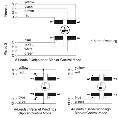
  • Connection : 4 leads Serial Windings Bi-polar

I was found the DRV8426 part and perform the primary functional test using DRV8426EVM. The setting parameter are as follow;

  • Software : DRV84xx EVM
  • Control Mode : Step
  • Step Mode : 1/256 step
  • VREF Voltage : 0.16 V
  • Speed : 8000
  • Decay Mode : Smart Tune Ripple Control
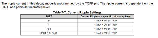
  • TOFF : 300 kohm to GND
  • VM : 12 V

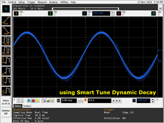
I got the following result using the oscilloscope, yellow line is output voltage of AOUT1, green line is output voltage of BOUT1 and blue line is output current of AOUT1.

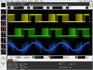
I was control the value of VREF to reduce jitter performance, and this result is one of the best. However, I want to reduce jitter performance more.

Q1. is DRV8426 is suitable solution to control the above motor?

Q2. How to reduce the high frequency factor in the blue line (Current Output)? Does this factor affect the jitter performance?

Q3. I can change the motor connection to 4 leads parallel winding bi-polar. I guess that specifications were changed as follow;

  • Resistance : 45 ohm
  • Inductance : 22.5 mH

If i change the connection from serial to parallel, the jitter performance to be better or not?

Could you help me to solve this issue?

Thanks & Best Regards,

Byeongsu, Kang

  • Hi Bryeongsu,

    This application note provides useful guidelines for reducing audible noise in stepper motors. 

    Regards,

    Pablo Armet

  • Hi Pablo Armet,

    Thanks for your advice. I reading a application note, and found the three key points.

    First, Increase the PWM Frequency.
    In my case, I am already using STRC and 1/256 Microstepping function. Therefore, in order to increase the PWM frequency, it is expected that the characteristics of the motor must be changed. I have plan that changing the motor connection from a serial winding to a parallel winding, and I think that L and delta I can be reduced through this. This is because the parallel winding has a lower impedance than the serial winding. Is this the right solution?

    Second, Reduce the Zero-cross Error.
    In order to reduce the zero-cross error, it is explained to reduce the Toff value. However, it is explained in the datasheet that the Toff value is set automatically when using the Smart Ripple Control function in the DRV8426. The following text is an excerpt from the text described in the datasheet. 'The TOFF pin configures the PWM OFF time for all decay modes except smart tune ripple control.' If I use the smart ripple control, even if the Toff value is adjusted, it will not applied. Is it right?

    Third, Increase the Step Frequency.
    Unfortunately, I already used 1/256 microstepping, and I couldn't find a way to increase the step frequency based on the same speed.

    Is there any way to further reduce the jitter performance based on the current setup and DRV8426?

    Thanks & Best Regards,

    Byeongsu, Kang

  • Hi Byeongsu,

    I have plan that changing the motor connection from a serial winding to a parallel winding, and I think that L and delta I can be reduced through this

    Can you clarify what you mean by this statement? 

    'The TOFF pin configures the PWM OFF time for all decay modes except smart tune ripple control.' If I use the smart ripple control, even if the Toff value is adjusted, it will not applied. Is it right?

    In smart tune ripple control, the TOFF pin is used for setting the ripple current at a specific step. TOFF pin tied to GND will set the lowest ripple possible and lower noise levels.

    Is there any way to further reduce the jitter performance based on the current setup and DRV8426?

    STRC, high step rate, and lower current ripple is the best combination for lower noise levels. Please set TOFF to GND (0) to set lowest current ripple if not done so already. 

    Regards,

    Pablo Armet

  • Hi Pablo Armet,

    First of all, I can understand, even if used the Smart Ripple Control function, can be adjust Toff parameter.

    In case of motor winding topic, the motor datasheet describes the following electrical connections;

    I can change the winding connection either parallel or serial, because my motor mentioned in the text above is '8-leads / Unipolar or Bipolar Control Mode'. When I first designed, I used Serial Winding. But, the jitter performance was too higher, so I had been asked a question. If I need to increase the PWM frequency, I think the only option for me is to change to parallel winding except for changing the motor itself.

    Thanks & Best Regards,

    Byeongsu, Kang

  • Hi Byeongsu,

    From the motor data (lets assume it was given for full step mode) we can calculate motor current of windings in series 12V/180 Ohm = 0,067A, for parallel connection it would be 0,133A. Both these current values are very small comparing to full scale current of DRV8426 which is 1.5A. Parallel connection in that case would be much better (better current regulation, its accuracy, possible higher motor speeds). I think additionally it would be worth of trying driver with lower full scale current like DRV8428 (1A).

    Regards,

    Grzegorz

  • Hi Grzegorz Pelikan

    Thanks for your advice. Unfortunately, I cannot change parts to DRV8428. Because the PCB has already been manufactured according to the DRV8426. I would like to find the optimal solution in the current configuration if possible.

    After change the motors connection to parallel, I was get an optimal waveform. Of course, this waveform was very clean because it measured the output current of the motor without a load.


    By the way here another question arose.

    STRC, high step rate, and lower current ripple is the best combination for lower noise levels.

    I obtained better results using STDD (Smart Tune Direct Decay) than STRC (Smart Tune Ripple Control). Of course, since it is a waveform measured without a load, the result may change after the final assembly is completed. However, I won't be able to check right away because I need help from the other team to get the final result waveform.

    Thanks & Best Regards,

    Byeongsu, Kang

  • Hi Byeongsu,

    Thanks for sharing the waveforms. I have no experience with DRV8426 but from datasheet we can see that STRC mode tries to keep current ripple at 11mA + % of ITRIP what is quite significant value comparing to your motor current. I think It is the main reason why STRC mode will not be suitable for your motor. On the second waveform switching frequency is changing from around 1,5kHz to somewhere around 10-20kHz and probably is causing some noise. The first waveform looks very clean and probably gives you the best results. On both waveforms peak current value is around 230mA what gives 230/1,41 = 163mA rms. I would verify if 163mA is not higher than motor rated current for parallel connection. Running motor at currents higher than motor rated current can not only damage it but may also increase noise and vibrations.

    I think the best method of running your motor will be the method that works for you. If you want to be prepared for possible problems I would:

    - run motor to speed where current starts to decrease and can not keep its shape - it will define your max. motor speed (usually it is possible to go faster but it means more troubles)

    - check for any resonances from standstill to your max. speed, if there are any you may need to limit their value or avoid their frequencies (load may change those frequencies a bit).

    Regards,

    Grzegorz

  • Hi Byeongsu,

    The STRC and STDD performance can differ from motor to motor and there can be many factors such as motor inductance, resistance, current that affect the performance of each decay mode. We recommend the STRC for lower jitter and noise levels based on experiments that we have conducted with various motors. In these experiments, STRC produces lower noise levels for most cases. But there can be a situation where STDD provides better results. If STDD provides better results for your application, please use it. 

    Regards,

    Pablo Armet