Other Parts Discussed in Thread: DRV3205-Q1
Hello,
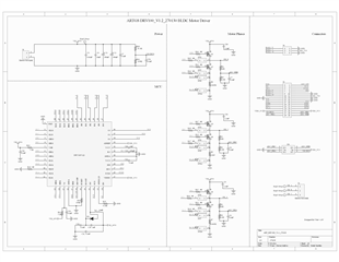
I'm Betul from Altınay Robot Technologies. I designed a BLDC motor driver with DRV3205-Q1 IC. During the first tests I had some troubles about driving the mosfets. When I supply the board with 24V and activate the Enable pin, all the high side gate outputs of the IC gets logic high and I can't change them to low with uploading code. That's why the 3 phases of the motor active at the same time and I can't control the outputs. I checked the high and low inputs (IHSx,ILSx) with osciloscope and tere's no problem, the PWM signal that I send from the code is generating on the inputs. But the outputs doesn't change. I use 0 ohm gate resistors is that cause this problem or should I check something else? Maybe the IC needs some configuration at the first time but I don't find anything about it or SPI communication on the documents on your website. Can you share some detailed documents about the IC and an example code of motor controlling with DRV3205-Q1?
Thanks& Best Regards,
Betul Yurddas