This thread has been locked.

If you have a related question, please click the "Ask a related question" button in the top right corner. The newly created question will be automatically linked to this question.

DRV8701EVM: how to modify it to control a single-phase BLDC motor?

Part Number: DRV8701EVM
Other Parts Discussed in Thread: DRV8701

https://www.ti.com/lit/ug/tidubb1/tidubb1.pdf?ts=1669431473519&ref_url=https%253A%252F%252Fwww.ti.com%252Ftool%252FTIDA-00875

Hi Team,

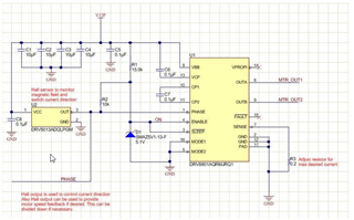
I refered the link above for modifying DRV8701EVM to control a single-phase BLDC motor.

I'm wondering how to provide power supply to the external hall sensor?

And can I use the DRV8701EVM GUI to control the BLDC motor after modification?

Kind regards,

Katherine

  • Hi Katherine,

    You may want to use an external power supply for the hall sensor or use the one from the EVM. If you wish to use the same voltage for the hall sensor as the DRV8701, you can use a wire to connect the VM and GND supply to the hall sensor. Otherwise, another external supply is needed.

    Regards,

    Pablo Armet

  • Katherine,

    First, you will need a DRV8701E device which is the PHASE/ENABLE variant.  Once you have this, the connections to the PHASE/ENABLE pins can be done exactly like the DRV8801A shown in figure 5 of the app note you refence.  

    If you need speed control, the ENABLE pin can be PWM'ed....this is also discussed if you read down just below figure 5.  

    The GUI is not required once configured with the hall sensor as all control will be closed loop with hall feedback.  

    Hall can be powered from a supply between 2.5V-38V, so it can share the the same supply as the DRV8701E.  However, a pull-up to DVDD on the output of the hall should be provided so the PH input is not over-voltage.  

    Connections to the EVM are shown in section 4.1.2 of the app note.  The device on the EVM is the "E" variant, so an EVM can be directly modified per instructions.

    Regards,

    Ryan

  • Hello,

    According to the steps in app note 4.1.2, shall I use an additional controller instead of the MSP430 module on the board? While the PWM signal is provided by an external controller, should the Hall output be connected to the external controller to handle switching phases?

    Kind regards,

    Katherine

  • Hi,

    an external controller is needed if you plan on running your own custom firmware. If that’s the case, the hall sensor output should be connected to external controller

  • Hello,

    Does the method in the app note still involve using the MSP430 on the board? If so, do I need to make modifications to the program?

    Kind regards,

    Katherine

  • Katherine,

    You can use the MSP430 in the EVM. No modification are needed if you don't plan on monitoring the hall sensor output with the controller. In the reference design, the output of the sensor is fed back to the PH of the driver. The duty cycle of the EN pin can be controlled via the included GUI and FW.

    Regards,

    Pablo Armet

  • Hi Pablo,

    My goal is to use EVM to control single-phase BLDC with Hall feedback. According to the first step in the reference design in the app note, removing the 0-ohm resistor is equivalent to disconnecting the connection with the MSP430? So, would an external controller be used? If I still have to use the MSP430 and the supplementary FW, I would like to know how to make the least changes to the EVM so as to control a single-phase BLDC's speed and clockwise and counterclockwise rotations with Hall feedback.

    Regards,

    Katherine

  • Hi Katherine,

    According to the first step in the reference design in the app note, removing the 0-ohm resistor is equivalent to disconnecting the connection with the MSP430?

    That's correct

    If I still have to use the MSP430 and the supplementary FW, I would like to know how to make the least changes to the EVM so as to control a single-phase BLDC's speed and clockwise and counterclockwise rotations with Hall feedback

    I am not very familiar with BLDC control as I work in the brushed and stepper group. Let me talk to the BLDC team and get back to you as soon as possible,

    Regards,

    Pablo

  • Hi Katherine,

    The schematic below shows the modifications needed. The VCC of the external hall sensor can come from the on-board regulator. The output of the hall sensor s tied directly to the PH pin. So the only signal you need to disconnect from the onboard MCU is PH. All the other signals can be left connected to MCU. No firmware changes is required if the modifications is the same as the one below. 

    I hope this answers all of your questions.

    Regards,

    Pablo