This thread has been locked.

If you have a related question, please click the "Ask a related question" button in the top right corner. The newly created question will be automatically linked to this question.

MCF8316AEVM: PI loop control and start-stop overshoots

Part Number: MCF8316AEVM
Other Parts Discussed in Thread: MCT8316A, MCF8316A, MCT8316Z

Dear community,

  • During the tuning of the MCF8316AEVM, I found that when the PI controller is not well adapted, the motor under load is vibrating at a fix shaking frequency (around 30Hz) with these following visible current peaks on the main VM wire:

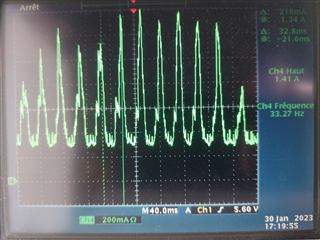
This vibrating behavior disappears if the PI settings are not so agressive.

What is the source of this frequency? Is it the PI controller treatment period? This value is fix, even if I change any settings, pwn frequency or speed. 

If it comes from a setting register, it would be interesting to increase this frequency in order the PI controller reacts faster and adapt better the speed and torque.


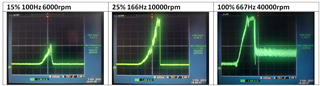
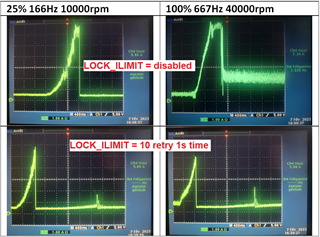
  • Also, sometimes, when I start or stop the motor, it presents rough 8A short overshoots on the main (VM wire) current:

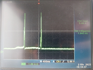
  <=== here a start followed by a stop, motor is rotating between both overshoots

How to prevent these peaks?

I have the feeling that these peaks are generated when we switch from open loop to closed loop and closed loop to brake procedure.

When the PI controller values are set manually the peaks behavior seems higher than when Ki Kp values are 0 and auto tuned, then the peaks are less often present and limited by the ILIMIT current value. Where can we read the auto tuned Ki Kp values?


Thank you in advance. My motor parameters are: 24VDC, 40.000rpm max, 1.35R, 0.09mH, 17mV/Hz (from MPET), 8.2A stall current.

Best Regards,

Julien

  • Hi Julien,

    Thanks for the details. We recommend using the auto-tuned speed loop Kp and Ki. If you wish to manually tune the Kp and Ki, please follow the procedure mentioned in section 2.2.2 in this app note

    Can you provide more details on the end equipment that you are working on? Does the load change dynamically? What is the motor phase current at 100% torque? 

    Regards,

    Vishnu

  • Hi,

    hat is the source of this frequency? Is it the PI controller treatment period? This value is fix, even if I change any settings, pwn frequency or speed. 

    It is called too high gain leading to oscillation in closed-loop control; or overshoot. At 30Hz oscillation, this is not caused by the I term in the PI control, but due to too high in P term. Reduce P to avoid oscillation. 

    What is your application -- speed or position control?

    Brian

  • Hi Vishnu and Brian,

    The application is for drill hand tool and requires to apply varying load on the rotor and to remain constant speed with increasing torque.

    I have another question. does the MCT8316A integrated trapezoidal control presents better performances than FOC for the application?

    Thanks!

    Regards,

    Marvin

  • Hi Marvin,

    The application is for drill hand tool and requires to apply varying load on the rotor and to remain constant speed with increasing torque.

    I have another question. does the MCT8316A integrated trapezoidal control presents better performances than FOC for the application?

    It makes sense to use PI loop to control drill hand tool speed.

    The issue here is about the PI control loop, not FOC or trapezoidal 6-step commutation for BL.

    If this is a speed control, then the 30hz oscillation can be due to the I term (integration) sampling is too fast causing overshoot then the negative speed error caused it to undershoot, cycling again and again. Start with slow I sampling and low gain, then slowly increase until achieve a stable speed control.

    What do you use for the motor speed feedback? Hall sensor or encoder?

    Brian

  • Marvin,

    I'll get back to you tomorrow, 

    Regards,

    Vishnu

  • Hi Vishnu,

    Thank you. I will wait for your response.

    Regards,

    Marvin

  • Dear All,

    Many thanks for your helpful suggestions.

    I tried the 2.2.2 and I could measure Iq = 2.00A and deducing Iq reference = 2.20A. When I switch to closed loop, the max speed is 697Hz. Then I use the Kp Ki equation 2000/697 = 3 = Kp and Ki = 0 but I am not satisfied by these results. 2000 is the good value for 2A? And speed loop Kp is limited to 2.55 in the settings so the value seems strange.

    With my own tuned settings I applying the load until the motor stalls I have the following VM wire current measurements:

    I would need at 6000rpm to allow not 2A but also 6/7A performances, the speed loop Kp Ki tuning could be sufficient for this?

    Also, after the motor is stopped by overload (see the 25% 100% pics), there is no GUI red fault alert (I disabled the ILIMIT locked faults), but my motor doesn't try to continue to work and remains to 0A or is blocked on an abnormal 2A current without rotor turning. It will turn again only if I change the I2C speed command. Sometimes I have to help the rotor by turning by hand in order it can start to turn again. How could I have a motor restarting every time the motor is blocked?

    EDIT: if I enable the LOCK_ILIMIT to maximum 8.0A, after an overload the motor stops and restart fine after 1 second time (LCK_RETRY):

    But we can observe that the driver allows less maximum current/torque on the motor performances than previously without ILIMIT. How to profit the best performances without limiting the current and with a good restarting after blocking (perhaps the locked detection/braking is too fast)?

    EDIT2: even if the LCK_RETRY LOCK_ILIMIT are set to 10 retry attempts, at the beginning the motor restarts fine alone but after some blockings by overload the LOCK_ILIMIT fault is Red but there is no retry processing until I clear the fault through the GUI. The retries are not working every time? Can we clear the faults manually on the EVM?

    Thank you in advance.

    Best Regards,

    Julien

  • What do you use for the motor speed feedback? Hall sensor or encoder?

    Dear Brian, my motor is sensorless.

    So regarding between MCF8316 and MCT8316 you have no preference suggestion for my application?

  • Hi Marvin,

    MCF8316A has algorithm integrated in it to measure the motor electrical and mechanical parameters and auto tune speed and torque Kp and Ki gains based on these parameters. I would recommend you to run the Motor Parameter extraction tool (MPET). You can find more details in section 2.2.1 in this app note.

    Regards,

    Vishnu

  • Hi Julien,

    Thanks for posting your question in MD forum. For easy tracking, can you post this question in a new thread by clicking "Ask a related question" on top right of this page? This can help us track the conversations better.

    Regards,

    Vishnu  

  • Hi Julien,

    Dear Brian, my motor is sensorless.

    So regarding between MCF8316 and MCT8316 you have no preference suggestion for my application?

    MCF8316 is for sensorless motor and only for speed control app (not stop and go as in position control), such as continuous running fan, pump.

    MCT8316 is for Hall sensor motor and it can be used for any application, speed or position control.

    For drill hand tool, which might need to start running with load (drill bit jammed in piece of wood or metal), the MCF8316 will not be able to initialize the motor rotor position using Align and IPD modes, because motor cannot free spin in open loop. For sensorless motor, the drill has to start spinning with no load first to commanded speed, then the drill bit can be insert into the load. This doesn't sound like a good versatile product. Therefore, I would think the proper choice is to use MCT8316 with Hall sensor motor, and you need a MCU to close the PI speed loop with its output single PWM fed to the driver PWM input.

    Brian

  • For sensorless motor, the drill has to start spinning with no load first to commanded speed, then the drill bit can be insert into the load.

    Hello Brian, 

    Thank you very much for all of these precisions.

    I understand that the best would be to use hall sensor. But we want to limit the wiring and to remain sensorless...

    Regarding the open loop control, in our application we only apply the load when we are in closed loop. We let the time to the motor to spin during the starting procedure with no load before to work, only with inserted drill bit small load. My setup seems to work because from 6000 to full speed I can spin the motor, reach around 6/7A but with some rough OL CL retry behaviors as described. Can them be adapted or does it mean the MCF8316 is not suitable with our application?

    Then if I want more torque on speeds under 6000 rpm with the MCx, the only way is to go on MCT8316Z hall sensor position for better than low BEMF behavior, right? Or the MCT8316A sensorless can help me to manage this with no load starting?

    Best Regards,

    Julien

  • I would recommend you to run the Motor Parameter extraction tool (MPET). You can find more details in section 2.2.1 in this app note.

    Hello Vishnu, thank you for answering fast.

    I already tried to auto tune by MPET tool but there is no better performances. Also Ki Kp are still on 0 value and not updated. When I set Ki 0,1 Kp 0,1 I already feel best performances.

    But as Marvin asked you, does the MCT8316A integrated trapezoidal control presents better performances than FOC for this application?

    Best Regards,

    Julien

  • Hi Julien,

    Regarding the open loop control, in our application we only apply the load when we are in closed loop. We let the time to the motor to spin during the starting procedure with no load before to work, only with inserted drill bit small load. My setup seems to work because from 6000 to full speed I can spin the motor, reach around 6/7A but with some rough OL CL retry behaviors as described. Can them be adapted or does it mean the MCF8316 is not suitable with our application?

    Sure you can control when to apply the load when the motor has got to high spinning speed, but what if the users already have the drill bit half way into a block of wood or metal, and so the motor is under load, then how does the sensorless motor starts in open loop? It will not be able to spin under load. For a drill hand tool, the condition of starting the motor under load should be expected. So I think using a sensorless motor for this application is not the right choice. 

    Then if I want more torque on speeds under 6000 rpm with the MCx, the only way is to go on MCT8316Z hall sensor position for better than low BEMF behavior, right? Or the MCT8316A sensorless can help me to manage this with no load starting?

    Sensorless motor CANNOT start up from zero speed under load. Your hand drill tool application requires the motor to be able to spin under load, so sensorless motor cannot work.

    You have to use a Hall sensor motor for this application with the MCT8316Z.

    Brian

  • But as Marvin asked you, does the MCT8316A integrated trapezoidal control presents better performances than FOC for this application?

    FOC speed control will give a smooth and quieter motor running when compare to trapezoidal 6-step commutation, as the 6-step is more quantize with rougher steps than FOC with smoother and higher resolution in commutation.

    But for the hand drill tool application, sensorless motor, regardless with FOC or 6-step trapezoidal, will not work as it cannot start to spin under load.

    Brian

  • Julien,

    Let me re-iterate. 

    For easy tracking, can you post this question in a new thread by clicking "Ask a related question" on top right of this page? This can help us track the conversations better. 

    This thread now has too many conversations containing multiple questions that cannot be utilized by the community, as they are unverified. Requesting you again to start a new thread by clicking "Ask a related question" on top right of this page.

    Regards,

    Vishnu

  • Hello Brian,

    Thank you for this comparison.

    Sure you can control when to apply the load when the motor has got to high spinning speed, but what if the users already have the drill bit half way into a block of wood or metal, and so the motor is under load, then how does the sensorless motor starts in open loop?

    I understand that this way of working will not work with sensorless under load. But actually, our application is not like a common wall driller but for medical purpose, as I mentioned we let the motor to reach the closed loop without load applied. If the motor starts under load, it should be stopped for security and restart when the load is released and then the motor can spin correctly before the user can apply again the load. Our specific application is "like" a hand drill tool but it is not for drilling wood or metal. It is for specific confidential application where the user doesn't start under load. The user has to release the load during the motor starting time, and this starting time has to be as fast as possible in order the user can apply again the load quickly.

    That why I insisted to try in starting under no load condition to have the better torque behavior under 6000rpm in sensorless mode. After 6000rpm the EVM with my drilling application starts and works fine. But under 6000rpm it is too weak, unstable and it doesn't start every time.

    Does it mean that my 40000rpm motor selected cannot work under 6000rpm because of low BEMF sensorless control?

    BEMF is 17mV/Hz (6000rpm = 100Hz = 1,7V?) from MPET, how can I calculate from this BEMF parameter and MCF settings the lower speed I can have a stable speed control and best torque?

    Could the Auto handoff Enabled parameter limits the low speed BEMF behavior? I changed from 0mV to 1500mV and it "seems" a few better.

    Thank you in advance.

    Best Regards,

    Julien

  • Hi Julien,

    I would recommend you to try the MCT8316A (Trapezoidal commutation) as you are looking for faster startup time and load during startup.

    Regards,

    Vishnu

  • Hi Julien,

    Our specific application is "like" a hand drill tool but it is not for drilling wood or metal. It is for specific confidential application where the user doesn't start under load. The user has to release the load during the motor starting time, and this starting time has to be as fast as possible in order the user can apply again the load quickly.

    This is much better description, and now I think you might be able to use sensorless motor. Since you only said a drill hand tool, I thought it was a common tool for wood and metal, etc with starting under load.

    But under 6000rpm it is too weak, unstable and it doesn't start every time.

    I'm not clear on this. Under 6000rpm, says 5000rpm, and you says it doesn't start every time? Why, it already spins at 5000rpm and it failed to start? Please be more clear. Do you mean when load is applied to drill at 5000rpm and it stalled? Then say so.

    Does it mean that my 40000rpm motor selected cannot work under 6000rpm because of low BEMF sensorless control?

    No. if a motor is rated to 40Krpm, it just means the max speed before things start to fly apart mechanically. You can check the motor BEMF constant Kb to see the generated voltage/rpm, then you can tell at what rpm its generated emf meets the driver cross zero threshold. I am sure this 40k rpm motor can close the loop at less than 6000 rpm during starting.

    BEMF is 17mV/Hz (6000rpm = 100Hz = 1,7V?)

    So Kb is 17mv/hz is the motor rating? Since Hz is the electrical cycle and not the mechanical speed, so you need to know how many electrical cycles per motor revolution. Says motor has 6 poles pairs (not 6 magnets but 6 pairs of magnet), then one motor revolution has 6hz, then you do the math.

    But under 6000rpm it is too weak, unstable and it doesn't start every time.

    I think your speed control loop is not good; could be due to very low speed resolution  feedback (driver only has the motor speed information from electrical cycles of the zero crossing detection, compared to using external encoder on motor shaft for high speed resolution information, says 100 lines encoder will give 400 counts per revolution using quadrature decoder). Low speed feedback resolution can lead to oscillation with high Kp and Ki gain, while high speed resolution would give high gain even at lower Ki and Kp for the PI loop. It bugs me to see that you wrote it doesn't start every time while it already runs at 5000 rpm (but under 6000rpm). It already runs at 5000rpm so why saying it doesn't start???

    Brian