Hi team,
Here's an issue from the customer may need your help:
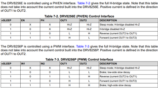
The DRV8256P is used to drive a 24-V DC motor with a maximum current of 2A, the chip's IN1 uses a PWM signal, 50 kHz, and in2 is normally low. Itrip is set to 2.5A and Toff is designed for 24us, slow decay mode.
When the duty cycle of the PWM signal is between 30% and 90%, the motor is hot enough with a temperature rise of 50 degrees C, while when the duty cycle is within 20% or 100%, the temperature of the motor is normal which is as the same as when driving a motor directly with a DC voltage.
1) Is the temperature rise of the motor with a PWM signal duty cycle between 30% and 90% ok?
2) What is the possible cause?
3) Is there any way to cool down?
Could you help check this case? Thanks.
Best Regards,
Cherry