Other Parts Discussed in Thread: DRV832X,
Unfortunately I can't answer to this broken forum.
https://e2e.ti.com/support/motor-drivers-group/motor-drivers/f/motor-drivers-forum/1194540/drv8323-t_dead-and-t_drive-with-software-deadtime/4504964?tisearch=e2e-sitesearch#
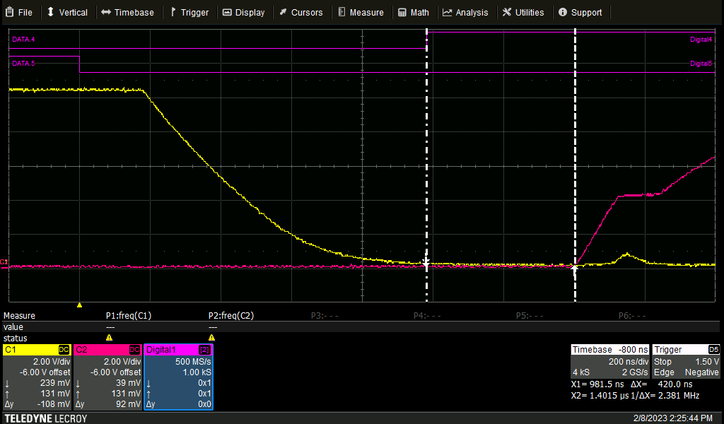
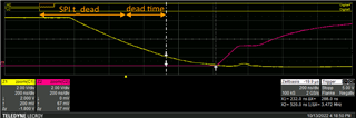
What I'm wondering is following picture.
You told:
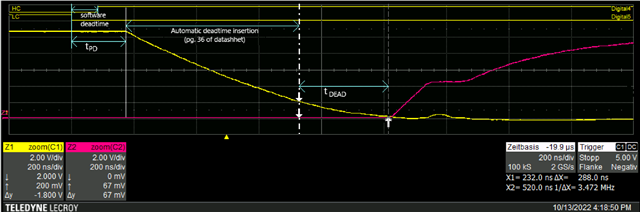
In your case, since INH is delayed 1000ns after INL, and so there is no potential of cross conduction, and the driver knows this, and so it doesn't need to add any deadtime in this case. This is why I said you don't need to add software deadtime between the inputs.
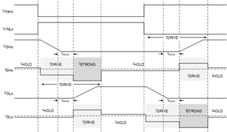
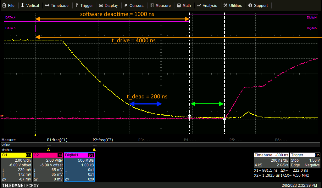
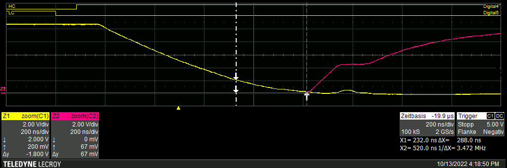
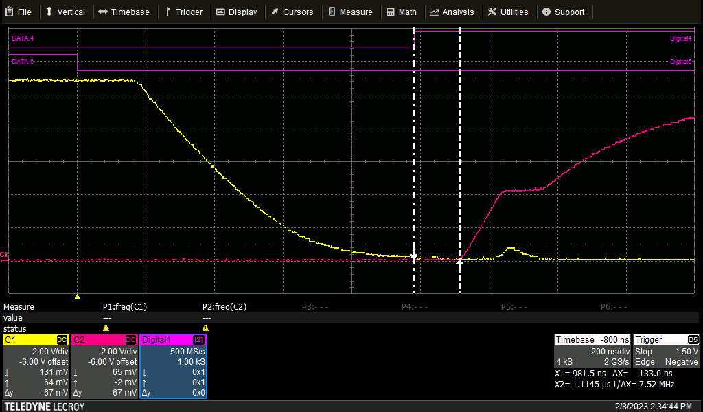
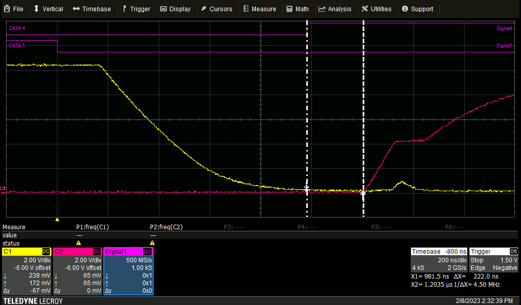
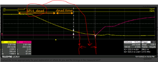
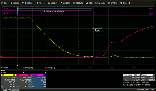
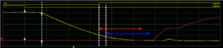
That's why I would expect a rising highside gate-source-signal (red) almost immediately after the change of INHx (Digital4), cause the t_dead should be already over. But in the measurements it seems, that the t_dead is added to the rising edge of the INxx input signal.
Can you please explain this to me a bit more detailed?

red: gate-source highside
yellow: gate-source lowside
software deadtime: 1000 ns
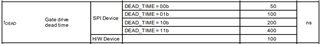
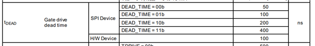
t_dead: 400 ns
t_drive 4000 ns
Kind regards
Tobias