Importance of Motor Parameters
When driving a sensorless 3-phase BLDC motor with field-oriented control (FOC), the control algorithm uses the motor parameters to create a mathematical model representation of the motor in order to estimate the rotor position and speed. The accuracy of the motor parameter directly impacts the accuracy of the estimated rotor position and the resulting torque/performance/stability of the sensorless FOC control loop.
Specifically, the crucial motor parameters needed for sensorless FOC control are:
- Motor Resistance
- Motor Inductance
- Motor Back-EMF Constant
These parameters can usually be obtained directly in the motor datasheet. However different motor datasheets may provide the parameters with slightly different criteria or units. For instance, the motor resistance can sometimes be given as phase-to-phase (aka line-to-line) resistance. This phase-to-phase resistance may need to be divided by 2 if the motor control algorithm expects the user to provide the phase resistance of a motor.
Be sure to check the criteria and units of the motor parameters that the motor control algorithm you’re using requires. For example, the MCF8316A integrated sensorless FOC motor driver expect the user to enter the motor phase resistance in Ω, motor phase inductance in mH, and motor back-EMF constant in mV/Hz
Measuring Motor Parameters
When dealing with a motor without a datasheet, the motor parameters can be measured by hand using an LCR meter and an oscilloscope.
Motor Phase Resistance
The motor phase resistance refers to the equivalent phase-to-center-tap resistance, RPH as shown in the figure below.
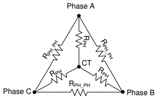
The equivalent RPH can be obtained by measuring the phase-to-phase resistance between any two phase terminals (RPH_PH), and then dividing this value by two, RPH = RPH_PH / 2. This measurement holds good for both Star (also called Y or Wye) wound and Delta (Δ) wound motors.
In star/wye wound motor, if user has access to center tap (CT), RPH can also be measured directly between center tap (CT) and any of the phase terminals.
Motor Phase Inductance
Similarly, the motor phase inductance refers to the equivalent phase-to-center-tap inductance, LPH as shown in the figure below.
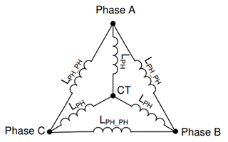
Use an LCR meter to measure the phase-to-phase inductance at 1 kHz across any two phase terminals LPH_PH, then divide this value by two to obtain the equivalent phase inductance, LPH = LPH_PH / 2.
Depending on the construction, some motors can have varying phase-to-phase inductance when the rotor is in different positions, known as the inductance/magnetic saliency of a motor. In such case, measure all three phase-to-phase inductances and calculate their average to use as the phase-to-phase inductance, LPH_PH = (LA_B, + LA_C + LB_C) / 3. Then divide it by 2 to obtain the equivalent phase inductance LPH.
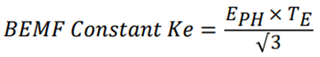
Motor Back-EMF Constant
The motor back-EMF constant describes the proportional relationship between the motor speed and the generated phase-to-center-tap back-EMF voltage as shown below.
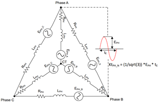
To determine the motor back-EMF voltage, use an oscilloscope and connect a voltage probe across any two phase terminals of the motor. Use your hand to manually spin the motor freely. A sinusoidal voltage waveform should appear on the oscilloscope. Measure the peak amplitude voltage EPH in milli-volts and time period TE in seconds as shown in the image above. Next calculate BEMF constant Ke in mV/Hz using the following equation: