Hi team,
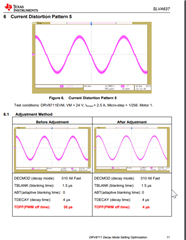
1) As shown by the blue arrow in Figure 1 below, the current in the figure still rises for some time after the Itrip decrease has entered the slow decrease. The customer thinks current will start to drop as soon as it enters slow decay, isn't it right?
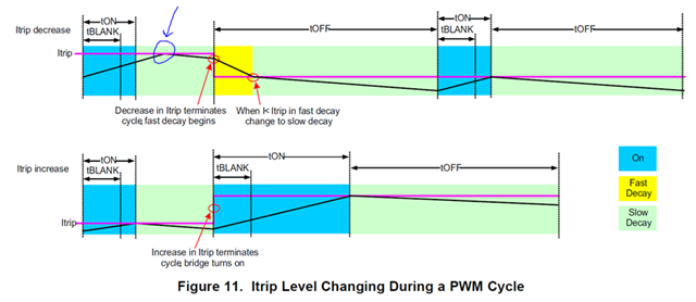
Figure 1.
2) The problem with mixed-decay mode near the current zero is as follows:
The test conditions are as follows:
- The stepper motor parameters are shown in the figure below, Model SST59D5305, with yellow markings
- The variant of the MOS tube is NCEP065N10gu_N100V90A_DFN5X6
- The registers are configured as follows:
ctrl reg: 0x341
torque reg: 0x178
off reg: 0x20
blank reg: 0x132
decay reg: 0x301
stall reg: 0x10f
drive reg: 0xaa0
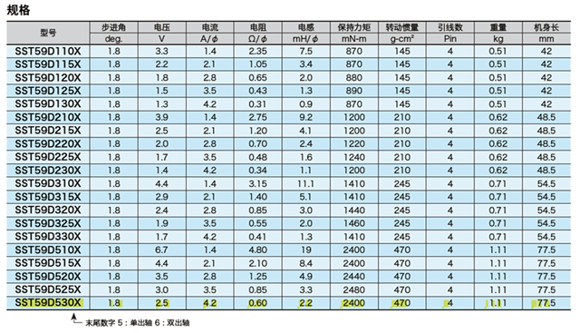
Figure 2.
As shown in the figure below, oscilloscope channel 1 (yellow) is high end, oscilloscope channel 2 (cyan) is low end, and oscilloscope channel 3 (purple) is high end. Oscilloscope channel 4 (green) is low end; channels 1 and 2 are on the H-bridge side, and channels 3 and 4 are on one side.
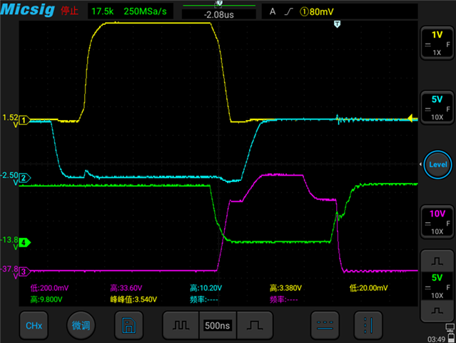
Figure 3. MOS Tube Gate Drive Voltage Waveform
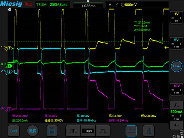
Figure 4. When the motor is stationary, the current is near 0 point, only 4 channels are replaced with coil current, the other three channels remain the same.
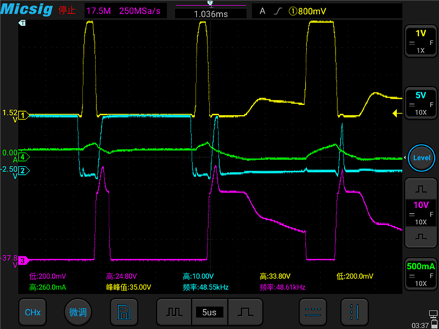
Figure 5. When the motor is stationary, the current is amplified near 0 point, only 4 channels are replaced with coil current, the other three channels remain the same.
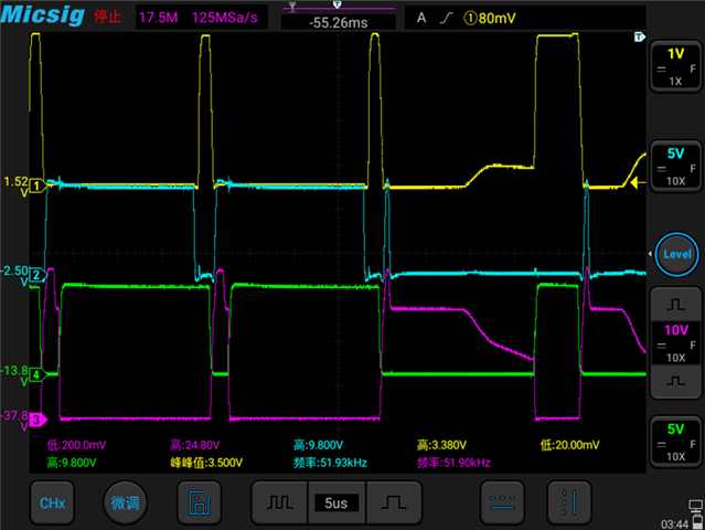
Figure 6. Motion of MOS tube when motor is stationary, near current 0 point.
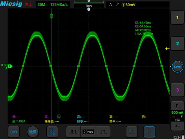
Figure 7. The current waveform when the motor is running is shown above.
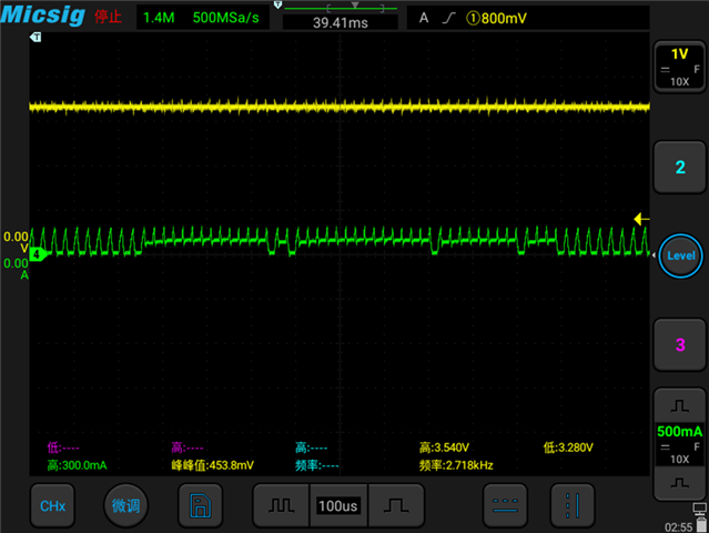
Figure 8. Current abnormal near 0 point, yellow fault pin, green motor coil current
As you can see from figures 4, 5, 6, 8, the magnitude of the change has changed with the motor at a standstill. Why?
Because in mixed-decay mode, it can be seen from the diagram that instead of entering slowDecay after fastDecay, all four MOS tubes were closed causing the current to continue to drop (body diode of the MOS tube).
Is it because the device detects any exception and then shuts down the MOS? But the fault pin does not change. And in the case shown in figure8, the noise is very loud.
3) Force fast decay at all times
In this mode, the current will be better near the current 0 point, but the current of the motor will change at a low frequency and the PWM frequency is high (because the off register value is small). The noise is also evident.
The device parameters are as follows:
ctrl reg: 0x341
torque reg: 0x178
off reg: 0x3
blank reg: 0x180
decay reg: 0x201
stall reg: 0x10f
drive reg: 0xaa0
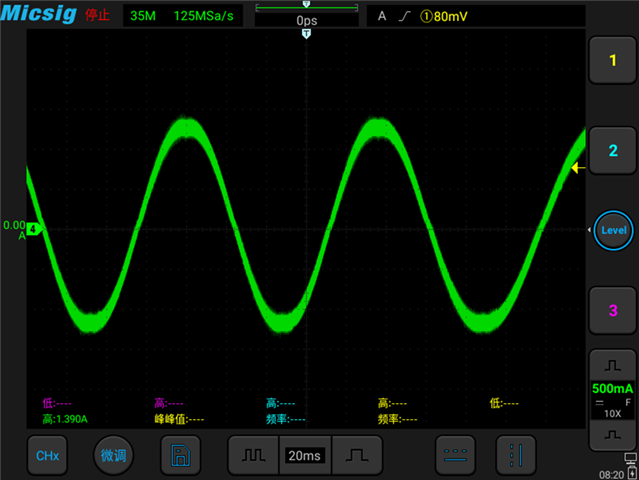
Figure 9. Current waveforms when the motor is running in force fast decay mode
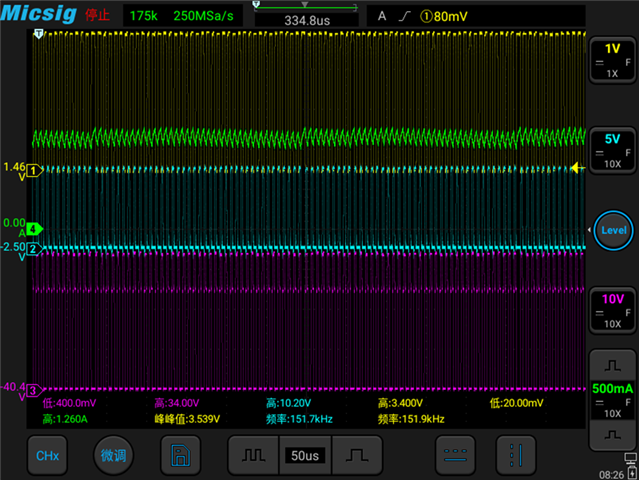
Figure 10. Force fast decay motor is stationary, 4 channel coil current variation
The customer also tried other decay modes, but it didn't work very well.
Could you help check this case? Thanks.
Best Regards,
Cherry