This thread has been locked.

If you have a related question, please click the "Ask a related question" button in the top right corner. The newly created question will be automatically linked to this question.

DRV8220: How to Blow Up

Part Number: DRV8220

What are the circumstances in which a DRV8220 DSG blows up?

A prototype PCB that controls a 600mA brushed dc motor uses a DRV8220 DSG to drive the motor in PWM mode at 100% duty cycle, and I managed to blow the driver up in what I think is normal operation! Was not paying too much attention to the circumstances when I heard a small pop after which the case of the driver had a hole in a place where previously there was none. Suffice to say, the driver no longer produces output. The motor was continuously moving in the same direction for some tens of seconds. Supply voltage was 12V. Half a minute later the board did not feel hot (didn't think to touch it any sooner). Board generally gets warm but not hot.

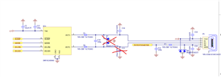
In the schematic we also included a ESD protection which is not present in the proto

If you can provide some suggestions for the next revision of our hardware, that would also be great?

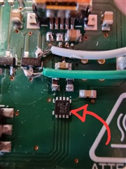
See here the schematic and the physical print after the incident.

  • Hey Jaakko,

    Thank you for your question.

    Please find my schematic review in the attached PDF. Usually damage like this occurs due to some sort of Abs max violation. I suggest looking into the bulk capacitances on VM as suggested in the pdf.

    DRV8220 Schematic Review.pdf

    Have you tried to recreate the damage? It would be helpful to measure the VM for any voltage spikes wrt to ground during operation and the motor output voltages and current. These can help paint a better story of what is happening.

    I also suggest looking at our DRV8220EVM board schematic and layout as guidance on board designs. 

    Best,

    Akshay

  • Hi Jaakko,

    I think C19 value is too high, please try to use lower value something like 1nF.

    Regards,

    Grzegorz

  • Summary: driver blows up when suddenly completely changing direction.

    How should we protect against this destruction both in hardware as well as in software?

    Update: I destroyed 2 more prints (totaling 3 destroyed). With both we replaced C2 with a 12V rated capacitor, which made the supply voltage very stable in our measurements. Other than C2, all components were already rated 12V or above.

    1. We thought that that was good enough and continued working on it. However, the ESD protection D7 which has 2 diodes and protects OUT1 and OUT2 was misbehaving the same way as the original print. That is, our otherwise symmetrical design worked in one direction and not in the other (the problem was not software, which we ruled out by measuring input and mode pin voltages). We removed the ESD suspecting a HW failure with it and carried on. Everything worked for a bit, so we dropped our guard, at which point that chip blew up while not paying attention.

    2. With our last print we were more careful. First we removed all filter components (F3, F6, C19, D7, C16, C21). Next, we drove the 12V motor in PWM mode at 100% duty cycle. First, forward, successfully (followed by braking). Then we drove the motor in reverse, also successfully (followed by braking). Next, while moving forward we changed polarity to reverse direction without braking first, at which moment the driver blew up instantly. VM was quite stable at 12V. OUT spiked very briefly to 13V. We did not measure current. (We suspect in hindsight that the ESD had in both earlier cases taken a hit from this same issue in an earlier instance, which would explain why we needed to remove this 'defective' component)

    I don't recall reading in the data sheet or user guide that you're not supposed to change direction suddenly like this. What can we do in software and in hardware to mitigate this issue?

  • Hey Jaakko,

    Thank you for the update. I will aim to provide feedback by Friday.

    Best,

    Akshay

  • Hey Jaakko,

    1. We thought that that was good enough and continued working on it. However, the ESD protection D7 which has 2 diodes and protects OUT1 and OUT2 was misbehaving the same way as the original print. That is, our otherwise symmetrical design worked in one direction and not in the other (the problem was not software, which we ruled out by measuring input and mode pin voltages). We removed the ESD suspecting a HW failure with it and carried on. Everything worked for a bit, so we dropped our guard, at which point that chip blew up while not paying attention.

    A - In this test what change did you do while testing from when it was working to when it blew up? The ESD diode needs to be rated to not blow up during normal motor commutation, and to account for slight fluctuations while stopping the motor or during direction change.

     2. With our last print we were more careful. First we removed all filter components (F3, F6, C19, D7, C16, C21). Next, we drove the 12V motor in PWM mode at 100% duty cycle. First, forward, successfully (followed by braking). Then we drove the motor in reverse, also successfully (followed by braking). Next, while moving forward we changed polarity to reverse direction without braking first, at which moment the driver blew up instantly. VM was quite stable at 12V. OUT spiked very briefly to 13V. We did not measure current. (We suspect in hindsight that the ESD had in both earlier cases taken a hit from this same issue in an earlier instance, which would explain why we needed to remove this 'defective' component)

    A - The sudden direction can cause voltage transient that can damage the driver. Would it be possible to share the OUT and VM waveforms when you ran this test? Generally we recommend slowing down the motor before changing direction to avoid damage from transients.

    Best,

    Akshay