Hi gents,
I'm recovering a design based on the DRV8231 to drive a Seemtoon 6VDC engine, but unfortunately i'm facing some issues.
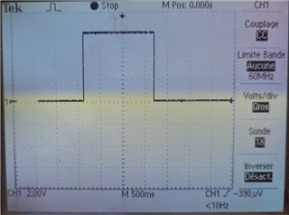
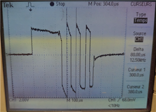
With Vm = 6VDC, when I pull down one of the INx pins when the engine is not connected i've got on the out1 / out2 +/-6VDC so all good.
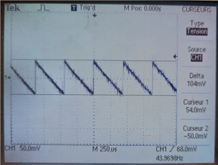
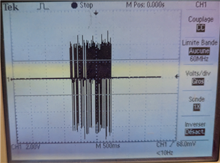
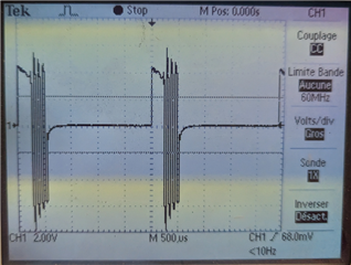
But when I connect the engine, the voltage drops to approximately 0.5V and the engine is not mooving, i've tried with a smaller engine and it works but voltage to the engine is arround 3V.
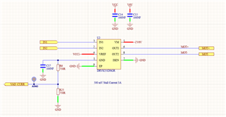
The design is as bellow, I've replaced R6 and R25 by O, I guess this was initially used to measure current consumption, and there is 2 33uF capacitors on Vm not showed on the schematics bellow.
VCC is 3.3V.
I appreciate any comment if you see something wrong.
Regards
Bruno