This thread has been locked.

If you have a related question, please click the "Ask a related question" button in the top right corner. The newly created question will be automatically linked to this question.

DRV8231A: Some motors stop when overdriven but will not restart until a power cycle

Part Number: DRV8231A
Other Parts Discussed in Thread: DRV8231, , DRV8873, DRV8874

I'm using some DRV8231ADDAR motor drivers to drive 130 sized brushed motors typical of what you might find on a radio controlled car.  We are a high school class using them in skid-steer style robots to play soccer, but it turns into Battlebots pretty quick..  Here's a video:  https://youtu.be/LldnpJlSyfI

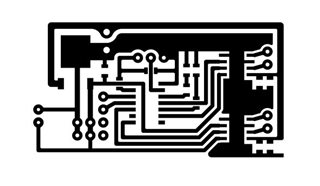
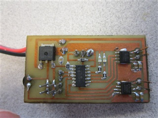
We designed and etched our own PCBs for this project.  The motors draw at least 10 amps at stall, but the great thing about these DRV8231 drivers is the 3.7A current limit keeps our 3D printed pinion gears from melting off of the shafts.  I am controlling them with a microcontroller where both input pins are high when the motor is not turning, and PWM a low pulse on one of the two pins to make it go.  I think the datasheet calls that "Brake; low-side slow decay".  My PWM frequency is 15626 Hz, I think.  My IPROPI pin is tied directly to ground.  My VREF is tied to the 5v line that powers my microcontroller.  My VM pin is connected to the positive side of a 2 cell LIPO battery, so about 7.4 - 8.4 volts.  That pin is also connected to ground through a .1uF and a 4.7uF capacitor.  

Everything is mostly working awesome, exactly as I expected it to.  However on some motors, the motor will stop when it gets too much load on it, and then won't restart until power is removed from the driver circuit and then plugged back in.  It's like it's not coming out of overcurrent protection.  When I change out the motor the problem goes away, and now I have about 5 motors (out of 22) that seem fine, and work with a regular power supply, but won't work on these circuits.  If I measure the voltage on the unplugged motor connection the voltage is what I would expect though, but the motor won't turn.  

I'm just a computer aided drafting teacher with hobby electronics experience, not an electrical engineer.  My oscilloscope is an analog scope, so I can't collect any output signals for analyzation.  

What could be causing this?

Brian Zweerink

  • Hi Brian,

    This is a very interesting project for your high school. I wish I had the opportunity to work on something like this when I was in high school.

    Everything is mostly working awesome, exactly as I expected it to.  However on some motors, the motor will stop when it gets too much load on it, and then won't restart until power is removed from the driver circuit and then plugged back in

    This points to some fault flag triggered by the DRV8231A that requires a device reset (power reset). Do you have the ability to measure the voltage and current of the outputs using an oscilloscope? Looking at those signals will help me get a better idea as to what is going on. If not, can you at least measure the output voltage when the driver is operating normally and when it stops.

    The motors draw at least 10 amps at stall, but the great thing about these DRV8231 drivers is the 3.7A current limit keeps our 3D printed pinion gears from melting off of the shafts

    This is concerning. 10A stall current is very high. I believe this may cause overtemperature shutdown if the stall condition persists for a long time. What is the steady state current of the motor? DO you have the ability to take a temperature measurement on the motor driver while it is in this stall condition? 

    Another possible solution is to limit the stall current using the integrated current regulation feature of the DRV8231A. 

    Can you share the datasheet or part number of the motor you are using? Also the schematic and PCB layout. You can share with me via private message if you don't wish to share in the public forum.

    Regards,

    Pablo Armet

  • Thank you for the input.  I think the mistake I have made is that I assumed that connecting IPROPI to ground without a resistor and VREF to 5v would give me current limiting at the maximum current allowed by the driver, but I am realizing that that is probably not true after your comments and a re-read of the datasheet.  I mean, it's limiting the current, but those chips are HOT!  I have not measured the temperature, but they get too hot to touch without pushing these robots very hard.  My motors draw .8A at free-running through our 3D printed gearboxes.  

    If I placed a resistor between IPROPI and ground to limit my current to 2 or 2.5 amps or so, would that solve my problems?  Or is limiting a 10 amp stall current motor with this type of technique considered bad practice?

    Ultimately I would love to find some 130 size motors with a 2A stall current, carbon brushes, and rated for 8V, but it is pretty difficult in the quantities I need.  It seems to go from 800mA from hobby robot shops like Pololu to 10+ amps for Nerf gun modification and RC cars, and there isn't much in between.  

    Thank you again for your input. 

    Brian Zweerink

  • Brian,

    If I placed a resistor between IPROPI and ground to limit my current to 2 or 2.5 amps or so, would that solve my problems?  Or is limiting a 10 amp stall current motor with this type of technique considered bad practice?

    Yes it would limit the initial inrush current and stall current but not the steady state current (0.8A) as it is much lower than 2A. Another thing to keep in mind is that the design of your PCB also matters. If you don't have enough GND copper on the thermal pad of the DRV, the IC temperature will be very hot. That's why it is recommended to have enough heat sinking on the PCB to dissipate the heat from the DRV. 

    The following resources provide useful information on PCB design guidelines for motor driver systems:

    I would review these two resources and compare to your PCB design. If you wish, I can review your PCB layout to see if the heat sinking is sufficient for the amount of power your motor and DRV are consuming.

    Ultimately I would love to find some 130 size motors with a 2A stall current, carbon brushes, and rated for 8V, but it is pretty difficult in the quantities I need.  It seems to go from 800mA from hobby robot shops like Pololu to 10+ amps for Nerf gun modification and RC cars, and there isn't much in between.

    Another option is to go for a higher current rated driver if you need to drive a high current motor. One suggestion is the DRV8874 (6A) or the DRV8873 (10A). 

    Regards,

    Pablo Armet

  • Here is my PCB design.  I'm not proud of it, and I don't have any PCB design software so I did it on Autodesk Inventor.  Nightmare.  

    And here it is soldered up.  The guide said to use vias, but doing this in the classroom we don't have a good way to do that, and this was a single sided PCB anyway.  I tried to make big ground pads underneath them.  You can see that there is probably too much solder under them, as I had to apply the paste with a syringe.  I have a laser and I'm going to try to make a solder stencil for next time.  

    I really, really wanted to use one of those higher current options, the DRV8874 or DRV8873, but I couldn't find them in quantities of less than 3000 when I was building these a month ago.  I'll try them though.   

  • Hi Brian,

    Have you tried using an open source PCB design software like KiCAD? I used this when I was in college and it is surprisingly good for being a free software. 

    I honestly do not think there is enough heat sinking on this board. Being single sided alone is a cause for concern specially at the high currents you are driving. I recommend at least a two layer board. 

    he guide said to use vias, but doing this in the classroom we don't have a good way to do that, and this was a single sided PCB anywa

    Are you building these boards by yourself? You can use a chinese PCB manufacturing company like JLCPCB. I also used them when I was in college. You can build a 2 layer board for about $2. Crazy cheap and the lead times are very quick as well. If your project timeline allows it, I would redesign your PCB and use JLCPCB to manufacturing the bareboards and you solder down the components. If you are going with the redesign route, I would choose the DRV8873 or DRV8874. You can order smaller quantities from digikey or mouser. 

    Regards,

    Pablo Armet

  • Thanks!  I will look into all of those things.  Yes, we are etching our own PCBs.  We have the toner transfer method down pat, and can do perfectly registered 2 sided boards.  We modified a laminator for the job.  I have a laser and can laser holes in the thru-holes instead of drilling them as well, so that part goes pretty fast as well.  Our art department has a kiln with a perfect reflow temperature profile. $2 is pretty cheap though, 

  • For the sake of posterity, I wanted to post an update on this problem.  I did indeed design my circuit without current limiting, by mistake, and my ground plane was too small to dissipate heat properly, BUT the reason some motors were working when others would not turned out to be the fact that my noise suppression capacitors were improperly soldered to the motor casing on some of the motors.  I do not understand exactly why this was causing the problems I was having, but in every case of a motor not coming out of an overload situation it was on a motor that did not have the capacitors soldered to the motor case properly.  I used three capacitors.  One between the terminals (and this alone was not enough, I tried just doing this) and one from each terminal to the motor case.  These capacitors were .1uF.  When soldered properly these drivers worked as expected.