This thread has been locked.

If you have a related question, please click the "Ask a related question" button in the top right corner. The newly created question will be automatically linked to this question.

MCT8316A: MCT8316AV Pin 22 to 24 marked as NC in data sheet but in the eval board the are connected to GND?

Part Number: MCT8316A
Other Parts Discussed in Thread: MCF8316A,

Hi

I have 2 project ( 2 different motors) that I want to realize with MCT8316AV.

Both motor works with the eval board.
But on my onw hardware they are not working.

If I connect my hardware via I2C it also working.
But if I use the local one I got in overcurrent an an error occurs.
Regiser CFS 0x0a0000000 I operate with 16V with 1A limit

I check all pins.so far I cound find a problem.

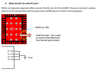
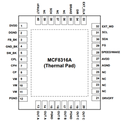
Then I realized that on the EVAL Board Pin 23 to 26 are all connected to AGND but the data sheet they are marked as NC?

Can this cause the problem?

Why the EVAL board is different to you recomendation?

Or do you have any idears?

My first motor is a 40W 23V very small drill motor ... runs with 2% non load.

BR

Andreas

  • Hi Andreas,

    Thanks for your question on the motor drives E2E forum. 

    The NC pins do not need to be connected to ground. Sometimes engineers do it for better heat dissipation but it depends on your application. See below:

    Can you send me your schematic so I can look over?

    Best,

    Robert

  • Hi,

    ok than this is not the resons for my problem.
    But will also do with GND in the next layout.
    Would be nice that you would mention that in the datasheet.

    I send you the data sheet. But must should be exact the same as the EVAL board.
    Only C34 was 100nF insted of 47... ( fixed that already...) but no change.

    5V creation is fine.

    3.3V LDO also fine.

    I2C I can read and write all.

    Only when I start the motor... I get into overcurrent and it stars beeping with high frequest.
    Power supply 17V 1A ( limited)
    But Setup works with the EVAL board. ( take the JSON) and converted to C Code.

    https://github.com/pfostenberg/MCF8316Json2C

    #include "mu_bldc_ti.h"
    void ti_init(void) {
    TI_I2C_bus_write(TI_MCx8316A_ISD_CONFIG,0x6F042080);
    TI_I2C_bus_write(TI_MCT8316A_MOTOR_STARTUP1,0x55480994);
    TI_I2C_bus_write(TI_MCT8316A_MOTOR_STARTUP2,0x052E3980);
    TI_I2C_bus_write(TI_MCT8316A_CLOSED_LOOP1,0x14620000);
    TI_I2C_bus_write(TI_MCT8316A_CLOSED_LOOP2,0x22B2C4F8);
    TI_I2C_bus_write(TI_MCT8316A_CLOSED_LOOP3,0x4CC40101);
    TI_I2C_bus_write(TI_MCT8316A_CLOSED_LOOP4,0x0009E9C4);
    TI_I2C_bus_write(TI_MCT8316A_CONST_SPEED,0x3FF01405);
    TI_I2C_bus_write(TI_MCT8316A_CONST_PWR,0x12C04504);
    TI_I2C_bus_write(TI_MCT8316A_150_DEG_TWO_PH_PROFILE,0x36DB6DA6);
    TI_I2C_bus_write(TI_MCT8316A_150_DEG_THREE_PH_PROFILE,0x36DB6D80);
    TI_I2C_bus_write(TI_MCT8316A_TRAP_CONFIG1,0x054BA106);
    TI_I2C_bus_write(TI_MCT8316A_TRAP_CONFIG2,0x3A880000);
    TI_I2C_bus_write(TI_MCT8316A_FAULT_CONFIG1,0x78F43025);
    TI_I2C_bus_write(TI_MCT8316A_FAULT_CONFIG2,0x7347FC09);
    TI_I2C_bus_write(TI_MCx8316A_GD_CONFIG1,0x1C440008);
    TI_I2C_bus_write(TI_MCx8316A_GD_CONFIG2,0x14400000);
    TI_I2C_bus_write(TI_MCT8316A_PIN_CONFIG1,0x2D720600);
    TI_I2C_bus_write(TI_MCT8316A_PIN_CONFIG2,0x080C0000);
    TI_I2C_bus_write(TI_MCT8316A_DEVICE_CONFIG,0x7FFF0000);
    TI_I2C_bus_write(TI_MCT8316A_PERIPH_CONFIG,0x00000000);
    TI_I2C_bus_write(TI_MCx8316A_SYS_STATUS1,0x014A0CCC);
    TI_I2C_bus_write(TI_MCx8316A_SYS_STATUS2,0x2001018F);
    TI_I2C_bus_write(TI_MCx8316A_SYS_STATUS3,0x0005002B);
    TI_I2C_bus_write(TI_MCx8316A_DEVICE_CTRL,0x06668000);
    TI_I2C_bus_write(TI_MCx8316A_ALGO_CTRL1,0x00000000);
    }

    Also if if conect the 2 I2C wires from my CPU to the EVAL board.
    all is fine.

    Any idear?

  • Hi Andreas,

    One thing I noticed is on the buck components. I notice you have two 10uF caps in parallel, however, we spec a lot of our datasheet performance based off a 22uF capacitor so we really recommend using a 22uF capacitor. See example spec below:

    I am not sure if this is causing your problem. 

    Are you using pins 36-38? I see you have pull down resistors to ground and labeled these pins as DACOUTs. Just a reminder, 38 is SOX and 36 and 37 are NC in MCF8316A:

    Also the cap between CPH and CPL needs to be 47nF per datasheet recommendation.

    What voltage is VCC/1.3D? Just make sure this voltage is above logic high voltage so nFault and others are getting pulled high.

    Best,

    Robert

  • Hi

    >>One thing I noticed is on the buck components. I notice you have two 10uF caps in parallel, however, we spec a lot of our datasheet performance based off a >>22uF capacitor so we really recommend using a 22uF capacitor. See example spec below:

    will check this next week.

    >I am not sure if this is causing your problem. 

    >Are you using pins 36-38? I see you have pull down resistors to ground and labeled these pins as DACOUTs. Just a reminder, 38 is SOX and 36 and 37 are >NC in MCF8316A:

    Sorry in the shematic I name it MCF .... but we switched to  MCT !
    because with the MCF - we could not reach the 35k RPM.

    Fine for MCT?

    >Also the cap between CPH and CPL needs to be 47nF per datasheet recommendation.
    Yes I already fixed that on the layout / PCB but no change.

    Do I need to change the chip ( Damaged?)

    >What voltage is VCC/1.3D? Just make sure this voltage is above logic high voltage so nFault and others are getting pulled high.

    MCP1755T-3.3 -> so 3.3V also meassured OK.

    BR

    Andreas

  • Hi Andreas,

    I will work to get back to you on this by the end of the week.

    Best,

    Robert

  • Hi Andreas,

    Most of your responses look like you have already found/resolved most of my recommendations. Your schematic does not feature the voltage ratings on the caps but as a reminder, in most cases we recommend ratings of 2x Vm to allow the caps to be able to handle voltage transients unless otherwise specified in the datasheet. 

    Also you can look at the EVM schematic and layout files on the MCT8316AEVM tool page to compare your designs side by side: https://www.ti.com/tool/MCT8316AEVM

    Sorry in the shematic I name it MCF .... but we switched to  MCT !

    No problem, should be okay if MCT.

    Do I need to change the chip ( Damaged?)

    I am not sure but this is something you could try just to eliminate the possibility.

    MCP1755T-3.3 -> so 3.3V also meassured OK.

    3.3V is good.

    Let me know if you need any additional help here.

    Best,

    Robert

  • Hi Andreas,

    If there are no more questions, could you please help mark this thread as resolved?

    I will close the thread for now, but feel free to open it again if you have an additional question around this topic.


    Best,

    Robert