This thread has been locked.

If you have a related question, please click the "Ask a related question" button in the top right corner. The newly created question will be automatically linked to this question.

DRV8876-Q1: DS questions

Part Number: DRV8876-Q1
Other Parts Discussed in Thread: DRV8876

Hi  team,

could you help to answer the following questions on DS? thanks 

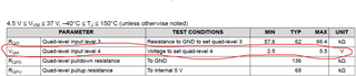
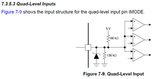
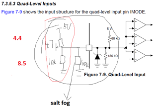
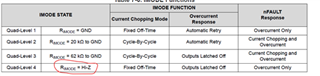
  • 1. IMODE configuration has 4 ways, Level 4 is the most suitable for customer application (ordinary DC motor running for long time), but there is a problem, the corresponding pulldown resistance is Hi-Z, That means dangling. As an input pin, the dangling is susceptible to interference, resulting in erratic operating conditions. Are there ways to improve?
  • Whether the PWM control mode can use 100% duty cycle 
  • What do PH and EN mean in PH/EN control mode? What is the abbreviation of the word? 

thanks 

  • Hello Hazel,

    For your first question, based on the datasheet, the IMODE pin is latched on power-up meaning that, after the device is awake, the IC will not change IMODE settings if there is a change in the IMODE pin as long as the IMODE pin is Hi-Z during startup.

    For the second question, according to the datasheet, in the applications of the DRV8876, regardless of if the intent is for bidirectional or unidirectional motor drive, the duty cycle and the H-bridge polarity are controlled with a PWM and IO resource from an external controller to the EN/N1 and PH/NH2 pins. Also, 100% duty cycle operation is supported on this device.

    For the third question, PH/EN control mode stands for Phase/Enable Control mode. For more information about PH/EN, this FAQ may help: https://e2e.ti.com/support/motor-drivers-group/motor-drivers/f/motor-drivers-forum/963987/faq-what-interface-ph-en-or-pwm-to-use-for-controlling-brushed-dc-motors

    Regards,

    Jaya Hari

  • Hi Jaya,

    thanks for your reply, about the first question,We still need to consider the following two situations:

    • This 1ms during device wake-up may also have interference coming in
    • The chip is in sleep state

    so are there ways to improve Interference ? thanks

  • I talked with Hazel Sun, besides her question, another my question is raised here:

    datasheet shows if the IMODE input voltage ranges from2.5V to 5.5V, the level 4 can be set during state transition. so is it true that I can add certain external circuit(such as resistor divider), together with the internal circuit, to set the IMODE voltage to 2.5~5.5V, instead of the Hi-Z(floating) connection for IMODE pin?


  • Hello Hazel,

    In the datasheet, figure 7-9 illustrates the Quad-Level input which is a divider network. In the case where the chip is in Hi-Z state, no current is sourcing through the IMODE pin. In this state, because the IMODE has specific voltage values for each of the 4 logic states, the IMODE voltage in State 4 will be around 3.33V. The pull-up and pull-down resistors included in the network are strong enough to prevent any sudden interference on the IMODE pin from changing its voltage.

    Regards,

    Jaya Hari

  • Hi, Jaya

    I talked with Hazel Sun, besides her question, other questions are raised here:

    1. datasheet shows if the IMODE input voltage ranges from2.5V to 5.5V, the level 4 can be set during state transition. so is it true that I can add certain external circuit(such as resistor divider), together with the internal circuit, to set the IMODE voltage to 2.5~5.5V, instead of the Hi-Z(floating) connection for IMODE pin?


    2. the pull-up and pull-down resistors are 68k and 136k, with pull-up source 5V. the steady current is 5V/ 204k = 24.5uA, which is not enough for anti-interference in my opinion. and what is more, the IMODE input voltage is easy to be changed in salt fog environment, because salt fog deposited on the PCB will cause the pull-down resistance decreasing, then the input voltage will fall into the LEVEL 3 range.

  • Hello Yanan,

    In terms of your first question, adding an external circuit may cause some problems as the internal circuit (as shown in Figure 7-9) will maintain the voltage around 3.3V when in Hi-Z.

    In terms of your second question, would an external 3.3 V voltage source (you can achieve this with a pull-up to an external 3.3V supply) attached to a limiting resistor that is connected to the IMODE pin in order to maintain a consistent supply such that you are able to maintain Level 4 (Hi-Z) while preventing a short.

    Regards,

    Jaya Hari

  • Hello, Jaya

    Happy talking with you and Pablo and Hazel today, about the IMODE level 4 Hi-Z configuration.

    2.5~5.5V on IMODE pin will make IC enter level 4 mode after waken up. with only the internal resistor divider participated, the IMODE voltage is 136/(136+68)*5=3.33V. but the internal pull-up and pull-down resistors are so high that the current is too low to resist strong external disturbance.

    So I prefer an external resistor divider with a lower value order(4.7k + 10k combination. 10k ohm order is 1 level order lower than the internal 100k ohm), to increase the current to maintain the IMODE voltage, as well as the anti-disturbance performance, while the IMODE voltage can be very slightly affected. the snapshot is the drawing I showed you in our meeting.  

    in my opinion, higher voltage and higher current on a signal trace make the signal stronger and more difficult to be changed by external disturbance.

    meanwhile, the external lower-value-order resister divider will make the circuit more robust against salt fog environment. Salt fog gathering together will leads to a equivalent pull-down resistor to GND (100k order or even less). without external resistor divider, the IMODE voltage will be decreased enormously, and maybe fall into level-3 voltage range. the external resistor divider has lower order resistors, which makes the voltage changed by salt fog slightly. level-4 voltage range is maintained in this way.

    the increased leakage current for semi-conductor devices due to higher temperature also has much less affect to IMODE voltage, with the external resister divider involved.