Welcome to a new FAQ series, Tackling BLDC Datasheets. A datasheet is the most comprehensive and accessible literature publicly available. Texas Instruments provides comprehensive datasheets presenting enormous amounts of information and data about an individual device, and the task of reading and understanding such information in terms of how it might be useful or critical to your particular application can be daunting. However, there are important terms and reading strategies which can speed up the research process and improve understanding of the overall device specifications. This FAQ series will provide a strategy for reading and understanding BLDC datasheets, as well as links to additional resources that dive deeper into each of the topics introduced here.
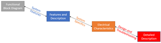
It is important to start with a strategy for reading and understanding a datasheet, which will improve the overall experience. There are many methods for reading a datasheet, but one possible way is to start by looking at the Functional Block Diagram of the device. This diagram provides a functional and structural overview of the device and can help you understand not only what the device is used for but also what features might differentiate it from other similar devices (such as integrated versus non-integrated FETs, buck regulators, or commutation control). Next, the Features section will provide more quantitative information on the power input and output capabilities of the device as well as any key functionality descriptions. Together, the Functional Block Diagram and Features sections describe the system features. Next, the Electrical Characteristics table provides the most comprehensive view of the device’s quantitative characteristics, such as recommended and maximum operating conditions, logic operating conditions, intrinsic values, and timing characteristics. Together with the Features section, it describes the specifics of the device. This information can be most useful in understanding whether a particular BLDC driver is right for your application. Lastly, the Detailed Description (and the rest of the datasheet) includes in-depth explanations about how the functional blocks work. This includes diagrams of Current Sense Amplifier outputs, PWM tables, pin diagrams, and fault & response tables. Together with the Electrical Characteristics, these sections are most useful in the design phase since they describe the various operations, programming requirements, and hardware characteristics of the device. These sections can also be referred to for debug questions since they provide the most in-depth information available in the datasheet and resources on device faults.
Each of these sections will be explained in more detail in subsequent FAQs, linked here. Please refer back to this FAQ in the future for all your questions about BLDC datasheets. The series flows according to the recommended strategy here:
Tackling BLDC Datasheets: System Features (link coming soon)
Tackling BLDC Datasheets: System Specifics (link coming soon)
Tackling BLDC Datasheets: Design and Troubleshooting (link coming soon)