Other Parts Discussed in Thread: DRV8317
I'm using the DRV8316EVM and have the DRV8316T ( non - SPI device installed).
I'm using the DRV8317EVM with the DRV8317T ( non - SPI device installed).
I'm using a controller that is sending 6 PWM signals to create an open loop current sine wave.
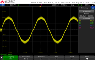
Scope Photo # 1 show the current into one phase of a BLDC motor using a standard discrete 3 Phase bridge. Note that I have no dead time crossing zero current.
When I use the DRV8316 with the same controller I see Photo #2. Note the distortions in the current waveform around zero current and the peaks.
The DRV8316 is configured,
Mode, 6 x PWM
Slew, 200V/us
OCP/SR, OCP = 10A, ASR AAR disabled.
When I use the DRV8317, I see a much better waveform as shown in Photo #3. Although there is still some distortion around zero current.
The DRV8317 is configured,
Mode, 6 x PWM
Slew, 200V/us
Why is the DRV8316 showing so much distortion in the open loop current waveform when compared to the DRV8317 and a standard 3 Phase discrete bridge design.
Is there some configuration that I'm missing for the DRV8316? Is there other data I can provide to help understand this issue? Please advise.
Thanks,
Roy
Scope #1, 3 Phase Bridge with discrete components
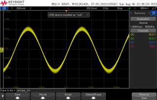
Scope #2, DRV8316
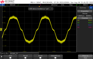
Scope #3, DRV8317