This thread has been locked.

If you have a related question, please click the "Ask a related question" button in the top right corner. The newly created question will be automatically linked to this question.

LAUNCHXL-F2800137: LAUNCHXL-F2800137 and BOOSTXL-DRV8323RS eval kit - DMC_BUILDLEVEL DMC_LEVEL_2 (The BLDC motor just keep cogging and doesn't rotate continuously)

Part Number: LAUNCHXL-F2800137
Other Parts Discussed in Thread: BOOSTXL-DRV8323RS

Hi,

I'm trying to fix up LAUNCHXL-F2800137 and BOOSTXL-DRV8323RS eval kit together to drive a 12V BLDC motor. This BLDC motor is an off-the-shelf part, not recommended in TI's application notes.

Currently I'm stuck at DMC_BUILDLEVEL DMC_LEVEL_2. My BLDC motor just keep cogging when I set "motorVars_M1.flagEnableRunAndIdentify" to 1.

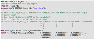
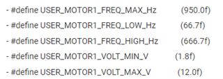
I just wish to check what's the parameters in user_mtr1.h that I need to modify correctly in order to make my customized BLDC motor to rotate continuously when DMC_BUILDLEVEL is set to DMC_LEVEL_2.

Hope to hear from you soon.

Regards,

Yip Kok Loong

  • Hello again,

    Per our previous conversation, you were able to run build level 1 and everything looked correct, given that the only estimator you are using is the HALL sensor- is that correct?

    Assuming that it is, please provide:

    • The excerpt of hal.h you created/adjusted for this motor
    • If possible, the relevant values from the motor datasheet

    Do note that given that you are using the HALL sensor and the behavior you're seeing, I'm wondering if it's possible that the HALL calibration sequence was not performed correctly. Can you run it again and confirm that you're seeing the same numbers that you've previously saved?

    Regards,
    Jason Osborn

  • Hi Jason,

    Yes, I'm able to run build level 1. Everything looks correct. The estimator that I'm using are MOTOR1_FAST and MOTOR1_HALL. As you have stated in my previous message to me, I need to include MOTOR1_FAST together with MOTOR1_HALL in the predefined symbol list in order to for phase voltage offsets (offset_V_sf) to be around 0.5.

    For build level 2, should I still enable MOTOR1_FAST together with MOTOR1_HALL in the predefined symbol list?

    Please take note that I have comment out those code that gave me error during code compilation when I enable MOTOR1_HALL in the predefined symbol list.

    In your last message, you requested me to run the HALL calibration sequence again and check whether am I seeing the same numbers that I have previously saved. For the numbers that you have stated, are you referring to the offset_I_ad and offset_V_sf parameters? If it is, yes, it's similar to what I have previously saved, very close to my previous values.

    I have attached my hal.h file below, fyi.

    The values that I have modify in user_mtr1.h to match my motor datasheet are stated below. I have also attached my user_mtr1.h file below.

    - #define USER_M1_NOMINAL_DC_BUS_VOLTAGE_V         (12.0f)

    - #define USER_M1_IA_OFFSET_AD    (2041.17993f)

    - #define USER_M1_IB_OFFSET_AD    (2030.27161f)

    - #define USER_M1_IC_OFFSET_AD    (2025.57312f)

    - #define USER_M1_VA_OFFSET_SF    (0.499066591f)

    - #define USER_M1_VB_OFFSET_SF    (0.496230334f)

    - #define USER_M1_VC_OFFSET_SF    (0.50050354f)

    - #define USER_M1_OVER_LOAD_POWER_W           (95.0f)

    - #define USER_M1_STALL_CURRENT_A             (20.0f)

    - #define USER_M1_FAIL_SPEED_MAX_HZ           (3000.0f)

    - #define USER_M1_FAIL_SPEED_MIN_HZ           (10.0f)

    - #define USER_M1_VA_OFFSET_SF_DELTA      (0.5f)

    - #define USER_M1_PWM_FREQ_kHz        (40.0f)

    - #define USER_M1_VS_REF_MAG_PU               (0.8f * USER_M1_MAX_VS_MAG_PU)

    - #define USER_M1_FWC_KI                          (0.0525f)

    - #define USER_M1_LOST_PHASE_TIME_SET             (1000U)

    - #define USER_M1_START_TIMES_SET                 (200U)

    - #define USER_MOTOR1_NUM_POLE_PAIRS         (1)

    - #define USER_MOTOR1_Rs_Ohm                 (0.13f)

    - #define USER_MOTOR1_Ls_d_H                 (0.000009f)

    - #define USER_MOTOR1_Ls_q_H                 (0.000009f)

    - #define USER_MOTOR1_RATED_FLUX_VpHz        (0.0022516660f)

    - #define USER_MOTOR1_MAX_CURRENT_A          (13.49f)

    - #define USER_MOTOR1_INERTIA_Kgm2           (2.1e-07)

    - #define USER_MOTOR1_RATED_VOLTAGE_V        (12.0f)

    - #define USER_MOTOR1_FREQ_MAX_Hz            (950.0f)

    - #define USER_MOTOR1_FREQ_LOW_Hz            (66.7f)

    - #define USER_MOTOR1_FREQ_HIGH_Hz           (666.7f)

    - #define USER_MOTOR1_VOLT_MIN_V             (1.8f)

    - #define USER_MOTOR1_VOLT_MAX_V             (12.0f)

    - #define USER_MOTOR1_OVER_CURRENT_A         (40.0f)

    - #define USER_MOTOR1_SPEED_START_Hz         (100.0f)

    - #define USER_MOTOR1_SPEED_FORCE_Hz         (50.0f)

    - #define USER_MOTOR1_GAIN_SPEED_LOW_Hz        (66.7f)

    - #define USER_MOTOR1_GAIN_SPEED_HIGH_Hz       (666.7f)

    - #define USER_M1_SPEED_CAP_MAX_Hz        (666.7f)

    - #define USER_M1_CAP_WAIT_TIME_SET       (200U)

    8713.hal.huser_mtr1.h

  • Hi Jason,

    Regarding those codes that I have comment out when I'm getting error during code compilation after I enable MOTOR1_HALL in the predefined symbol list, there are 2 lines of code that I have commented out in motor1_drive.c and motor_common.c.

    In motor1_drive.c,

    - line 3815, HALL_setTimeStamp(obj->hallHandle, HAL_calcCAPCount(obj->halMtrHandle));

    In motor_common.c,

    - line 295, HAL_resetCAPTimeStamp(obj->halMtrHandle);

    The reason why these 2 lines of code are being commented out is because the compiler stated that HAL_calcCAPCount and HAL_resetCAPTimeStamp are undefined symbol. I need to comment out these 2 lines of code in order for the compilation to be successful.

    Are these 2 lines of code that being commented out the root cause of the motor cogging issue?

    Regards,

    Yip Kok Loong

  • Hi Jason,

    There's another line of code that I missed out in my previous message:

    In motor1_drive.c,

    - line 3035, HALL_setTimeStamp(obj->hallHandle, HAL_calcCAPCount(obj->halMtrHandle));

    The code that stated above is being commented out in order for the compilation to be successful, fyi.

    Regards,

    Yip Kok Loong

  • Hi Jason,

    Just wish to check with you, should the value of EPwm3Regs.CMPA.CMPA be '0x0000' when motorVars_M1.flagEnableRunAndIdentify is set to '1' while running build_level_2?

    I notice that the value of EPwm1Regs.CMPA.CMPA and EPwm2Regs.CMPA.CMPA keep changing when motorVars_M1.flagEnableRunAndIdentify is set to '1' while running build_level_2, but only EPwm3Regs.CMPA.CMPA keep constant at '0x0000'.

    There's another thing. I notice that the CMPA value for EPwm6Regs keep changing when motorVars_M1.flagEnableRunAndIdentify is set to '1' while running build_level_2. Is it correct?

    Regards,

    Yip Kok Loong

  • Hi Jason,

    I think I know why CMPA value for EPwm6Regs keep changing whereas CMPA value for EPwm3Regs doesn't change when motorVars_M1.flagEnableRunAndIdentify is set to '1' while running build_level_2.

    In hal.h, line 625, MTR1_PWM_W_BASE is defined as EPWM6_BASE. It's the default setting in hal.h file for motor driver DRV8323RS. Should MTR1_PWM_W_BASE be defined as EPWM3_BASE instead?

    Please advise.

    Regards,

    Yip Kok Loong

  • Hi,

    I have captured waveforms of INA, GTA and MOTA on BOOSTXL-DRV8323RS eval kit. The pictures of these waveforms are attached below.

    The PWM signal at INA is running at 40KHz, fyi. From the first waveform, you will notice that the current waveform of MOTA signal has numerous spikes. This indicate that there are instances where current flow from MOTA to the stator winding of the BLDC motor, but seems like the current only flow for 375us (see second waveform). Almost all the current spike shown on the first waveform has similar pulse width (375us).

    From the first waveform, there's also a period where the current flow from MOTA to the stator winding of the BLDC motor for around 100ms (see third waveform).

    So, based on the waveforms that I have captured, can we roughly know what exactly is the issue that caused my motor not to turn continuously?

    Regards,

    Yip Kok Loong

  • Hello,

    Apologies for the delay in response, I was out of office- I will look into the information you sent and try and get back to you within 1-2 days.

    Regards,
    Jason Osborn

  • Hi Jason,

    Ok, noted with thanks. Will wait for your reply.

    I have tried to drive my BLDC motor by enabling the predefined symbol to MOTOR1_FAST only. It's still not successful.

    Is it due to the low stator coil inductance of my BLDC motor? The phase to phase inductance of the stator coil is only 18uH. Should I look into the parameters that meant for the PI controller?

    Regards,

    Yip Kok Loong

  • Hello,

    I'll go through your posts in order.

    • When I refer to HALL calibration, I refer to the MOTOR1_HALL_CAL predefined symbol. In your motor1_drive.c file, search for "const float32_t hallAngleBuf[7]"
      • Follow these instructions to calibrate the HALL sensor.
    • I would recommend running MOTOR1_FAST and MOTOR1_HALL together in every build level until the system is functional- it's very useful for debug, and is actually necessary for the HALL calibration.
    • HALL_setTimeStamp() and HALL_resetCAPTimeStamp() functions both exist in the hall.h file, but given that the F280013x UMCL project does not natively support HALL, they were removed for that device. Here's the code from the F28002x and F280013x, for comparison:
      • Code from the F28002x files:
        • hal.h:
          • #if defined(MOTOR1_HALL) && defined(CMD_CAP_EN)
            #error HALL and CMD_CAP can't be enabled at the same time
            #elif defined(MOTOR1_HALL)
            //! \brief      Sets up the CAP (Capture Subsystems)
            //! \param[in]  handle  The hardware abstraction layer (HAL) handle
            extern void HAL_setupCAPs(HAL_MTR_Handle handle);
            
            //! \brief      Sets up the CAP (Capture Subsystems)
            //! \param[in]  handle  The hardware abstraction layer (HAL) handle
            extern void HAL_resetCAPTimeStamp(HAL_MTR_Handle handle);
            
            //! \brief     Read the CAP counters
            //! \param[in] handle      The hardware abstraction layer (HAL) handle
            //! \return    The CAP counters
            static inline uint32_t HAL_calcCAPCount(HAL_MTR_Handle handle)
            {
                HAL_MTR_Obj    *obj = (HAL_MTR_Obj *)handle;
                uint16_t  cnt;
                uint32_t capSumCount = 0;
            
                for(cnt = 0; cnt < 3; cnt++)
                {
                    capSumCount += ECAP_getEventTimeStamp(obj->capHandle[cnt], ECAP_EVENT_2);
                    capSumCount += ECAP_getEventTimeStamp(obj->capHandle[cnt], ECAP_EVENT_3);
                }
            
                return(capSumCount);
            }
            #elif defined(CMD_CAP_EN)
        • hal.c:
          • #if defined(MOTOR1_HALL) && defined(CMD_CAP_EN)
            #error HALL and CMD_CAP can't be enabled at the same time
            #elif defined(MOTOR1_HALL)
            void HAL_setupCAPs(HAL_MTR_Handle handle)
            {
                HAL_MTR_Obj    *obj = (HAL_MTR_Obj *)handle;
                uint16_t  cnt;
            
                for(cnt = 0; cnt < 3; cnt++)
                {
                    // Disable ,clear all capture flags and interrupts
                    ECAP_disableInterrupt(obj->capHandle[cnt],
                                          (ECAP_ISR_SOURCE_CAPTURE_EVENT_1  |
                                           ECAP_ISR_SOURCE_CAPTURE_EVENT_2  |
                                           ECAP_ISR_SOURCE_CAPTURE_EVENT_3  |
                                           ECAP_ISR_SOURCE_CAPTURE_EVENT_4  |
                                           ECAP_ISR_SOURCE_COUNTER_OVERFLOW |
                                           ECAP_ISR_SOURCE_COUNTER_PERIOD   |
                                           ECAP_ISR_SOURCE_COUNTER_COMPARE));
            
                    ECAP_clearInterrupt(obj->capHandle[cnt],
                                        (ECAP_ISR_SOURCE_CAPTURE_EVENT_1  |
                                         ECAP_ISR_SOURCE_CAPTURE_EVENT_2  |
                                         ECAP_ISR_SOURCE_CAPTURE_EVENT_3  |
                                         ECAP_ISR_SOURCE_CAPTURE_EVENT_4  |
                                         ECAP_ISR_SOURCE_COUNTER_OVERFLOW |
                                         ECAP_ISR_SOURCE_COUNTER_PERIOD   |
                                         ECAP_ISR_SOURCE_COUNTER_COMPARE));
            
                    // Disable CAP1-CAP4 register loads
                    ECAP_disableTimeStampCapture(obj->capHandle[cnt]);
            
                    // Configure eCAP
                    //    Enable capture mode.
                    //    One shot mode, stop capture at event 3.
                    //    Set polarity of the events to rising, falling, rising edge.
                    //    Set capture in time difference mode.
                    //    Select input from XBAR4/5/6.
                    //    Enable eCAP module.
                    //    Enable interrupt.
                    ECAP_stopCounter(obj->capHandle[cnt]);
                    ECAP_enableCaptureMode(obj->capHandle[cnt]);
            
                    ECAP_setCaptureMode(obj->capHandle[cnt], ECAP_CONTINUOUS_CAPTURE_MODE, ECAP_EVENT_3);
            
                    ECAP_setEventPolarity(obj->capHandle[cnt], ECAP_EVENT_1, ECAP_EVNT_FALLING_EDGE);
                    ECAP_setEventPolarity(obj->capHandle[cnt], ECAP_EVENT_2, ECAP_EVNT_RISING_EDGE);
                    ECAP_setEventPolarity(obj->capHandle[cnt], ECAP_EVENT_3, ECAP_EVNT_FALLING_EDGE);
                    ECAP_setEventPolarity(obj->capHandle[cnt], ECAP_EVENT_4, ECAP_EVNT_RISING_EDGE);
            
                    ECAP_enableCounterResetOnEvent(obj->capHandle[cnt], ECAP_EVENT_1);
                    ECAP_enableCounterResetOnEvent(obj->capHandle[cnt], ECAP_EVENT_2);
                    ECAP_enableCounterResetOnEvent(obj->capHandle[cnt], ECAP_EVENT_3);
                    ECAP_enableCounterResetOnEvent(obj->capHandle[cnt], ECAP_EVENT_4);
            
                    ECAP_enableLoadCounter(obj->capHandle[cnt]);
                    ECAP_setSyncOutMode(obj->capHandle[cnt], ECAP_SYNC_OUT_SYNCI);
                    ECAP_startCounter(obj->capHandle[cnt]);
                    ECAP_enableTimeStampCapture(obj->capHandle[cnt]);
                    ECAP_reArm(obj->capHandle[cnt]);
                }
            
                XBAR_setInputPin(INPUTXBAR_BASE, MTR1_CAP_U_XBAR, MTR1_HALL_U_GPIO);
                XBAR_setInputPin(INPUTXBAR_BASE, MTR1_CAP_V_XBAR, MTR1_HALL_V_GPIO);
                XBAR_setInputPin(INPUTXBAR_BASE, MTR1_CAP_W_XBAR, MTR1_HALL_W_GPIO);
            
                ECAP_selectECAPInput(obj->capHandle[0], MTR1_CAP_U_INSEL);
                ECAP_selectECAPInput(obj->capHandle[1], MTR1_CAP_V_INSEL);
                ECAP_selectECAPInput(obj->capHandle[2], MTR1_CAP_W_INSEL);
            
                return;
            }   // HAL_setupCAPs()
            
            void HAL_resetCAPTimeStamp(HAL_MTR_Handle handle)
            {
                HAL_MTR_Obj    *obj = (HAL_MTR_Obj *)handle;
                uint16_t  cnt;
            
                for(cnt = 0; cnt < 3; cnt++)
                {
                    ECAP_setAPWMPeriod(obj->capHandle[cnt], 0);
                    ECAP_setAPWMCompare(obj->capHandle[cnt], 0x01FFFFFF);
                    ECAP_setAPWMShadowPeriod(obj->capHandle[cnt], 0x01FFFFFF);
                    ECAP_setAPWMShadowCompare(obj->capHandle[cnt], 0x01FFFFFF);
                }
            
                return;
            }   // HAL_resetCAPTimeStamp()
            #elif defined(CMD_CAP_EN)
      • Code from the F280013x files:
        • hal.h:
          • #if defined(MOTOR1_HALL) && defined(CMD_CAP_EN)
            #error HALL and CMD_CAP can't be enabled at the same time
            #elif defined(MOTOR1_HALL)
            #error This device and kit can't support Hall sensor based FOC
            #elif defined(CMD_CAP_EN)
        • hal.c:
          • #if defined(MOTOR1_HALL) && defined(CMD_CAP_EN)
            #error HALL and CMD_CAP can't be enabled at the same time
            #elif defined(MOTOR1_HALL)
            #error This device and kit can't support Hall sensor based FOC
            #elif defined(CMD_CAP_EN)
      • Assuming the other adjustments you've made for incorporation of the HALL sensor on the F280013x are correct, these changes also need to be made, and those lines should be uncommented. Given that you're also having this issue with just FAST, though, I don't believe this would be a root cause.
    • It is my understanding that the CCS debug import file is slightly out of date- it should be EPwm6Regs not EPwm3Regs in the debug window.
    • Leave it as EPWM 6, this is the correct ePWM.
    • Will skip the waveforms for now, as I want to address your most recent post first.
    • If MOTOR1_FAST is also not working correctly, this means that there are likely motor parameters that are incorrectly set, or something is physically wrong with the system setup. I also don't think I realized that this was a low inductance motor- these have a few special considerations which must be made:

    There were a lot of posts, so it's possible I missed something- please let me know if you have any other immediate questions.

    Regards,
    Jason Osborn

  • Hi Jason,

    Thanks for the advise, really appreciated!

    Will base on your input to try again and will try to get back to you by next week.

    Regards,

    Yip Kok Loong

  • Hi Jason,

    I have incorporated HALL_setTimeStamp() and HALL_resetCAPTimeStamp() functions into hal.h and hal.c files.

    The following additional codes were included while incorporating HALL_setTimeStamp() and HALL_resetCAPTimeStamp() functions into hal.h and hal.c files:

    - uint32_t       capHandle[3]; (hal_obj.h, line 235)

    - #define MTR1_HALL_U_GPIO 40 (hal.h, line 661)
    - #define MTR1_HALL_V_GPIO 41 (hal.h, line 662)
    - #define MTR1_HALL_W_GPIO 39 (hal.h, line 663)

    - #define MTR1_CAP_U_XBAR XBAR_INPUT7 (hal.h, line 665)
    - #define MTR1_CAP_V_XBAR XBAR_INPUT2 (hal.h, line 666)
    - #define MTR1_CAP_W_XBAR XBAR_INPUT3 (hal.h, line 667)
    - #define MTR1_CAP_U_INSEL ECAP_INPUT_INPUTXBAR7 (hal.h, line 668)
    - #define MTR1_CAP_V_INSEL ECAP_INPUT_INPUTXBAR2 (hal.h, line 669)
    - #define MTR1_CAP_W_INSEL ECAP_INPUT_INPUTXBAR3 (hal.h, line 670)

    The additional codes above were needed to be included in hal_obj.h and hal.h in order for the build compilation to be successful.

    Can you please help to check whether the additional codes above were implemented correctly?

    After the build compilation were done successfully, I tried to run the program and enabled motorVars_M1.flagEnableRunAndIdentify parameter. The motor still cogging, can't rotate continuously. I will take a look at section 6.10.1.5 and 6.10.8.1 of  InstaSPIN-FOC and InstaSPIN-Motion User's Guide and try out again.

    There's another thing that I need you to clarify.

    In your previous message, you advise me to search for "const float32_t hallAngleBuf[7]" in motor1_drive.c file and follow the instruction to calibrate the HALL sensor. In the instruction, it stated that copy hall_M1.thetaCalBuf[] to hallAngleBuf[]. Where to find hall_M1.thetaCalBuf[]? I couldn't find this variable.

    Regards,

    Yip Kok Loong

  • Hi Jason,

    I think I have found the hall_M1.thetaCalBuf[]. It's actually motorHandle_M1.hallHandle.thetaCalBuff[]. Can you please help to confirm whether motorHandle_M1.hallHandle.thetaCalBuff[] is the correct variable?

    For the HALL sensor calibration, it's not needed for Build Level 2, am I right? Based on my understanding, for build level 2, the system is running with open loop control, it doesn't need the feedback from the hall sensor output, right?

    Regards,

    Yip Kok Loong

  • Hello,

    For your first question, yes, it's the thetaCalBuff[] array in the Hall object, which is located in the main motor control object. I forgot that the name had changed since the writing of the comment in the code in this screenshot:

    For your second question, yes, that's correct- apologies, I realize now I was focusing on the HALL calibration aspect of your question instead of the build level 2 aspect. Taking another look at your predefined values, the following are the most important in Build 2:

    The advice I've been given in the past is to set these as follows:

    USER_MOTOR1_FREQ_MAX_Hz ~150% of USER_MOTOR1_FREQ_HIGH_Hz
    USER_MOTOR1_FREQ_LOW_Hz ~10 to 20% of USER_MOTOR1_FREQ_HIGH_Hz
    USER_MOTOR1_FREQ_HIGH_Hz Motor rated speed, per motor datasheet
    USER_MOTOR1_VOLT_MIN_V ~10 to 20% of USER_MOTOR1_VOLT_MAX_V
    USER_MOTOR1_VOLT_MAX_V Motor rated voltage, per motor datasheet

    Is this accurate to the values you have?

    Again, apologies for missing that aspect of your question.

    Regards,
    Jason Osborn

  • Hi Jason,

    Yes, the values that I have in the above parameters are within the specified range.

    I have questions on USER_M1_PWM_FREQ_kHz parameter:

    - Is there a specific value for USER_M1_PWM_FREQ_kHz parameter? The default value is 15. I set mine to 40. I notice that my motor's rotor tend to rotate when the USER_M1_PWM_FREQ_kHz parameter is set to 40, although the rotor tend to cog and will not rotate continuously.

    - Is there a formula to determine the value of USER_M1_PWM_FREQ_kHz parameter?

    - I manage to find 2 motors in TI website (see the 2 links below). Is it confirm that the setup consists of LAUNCHXL-F2800137 + BOOSTXL-DRV8323RS eval kit can drive the following motors? I may buy one of these motors to try it out.

    https://www.ti.com/tool/LVSERVOMTR

    https://www.ti.com/tool/LVBLDCMTR

    I'm still not able to make the motor to rotate continuously, fyi.

    Regards,

    Yip Kok Loong

  • Hello,

    USER_M1_PWM_FREQ_kHz is set to a value that is generally functional for most motors that the developer of this lab tested. This may not be the best value for all motors- first, check the motor datasheet. Some datasheets give a specific value for the PWM frequency required to run a given motor and/or the time constant of the motor, which can in turn be used to determine the ideal PWM switching frequency.

    If you determine a higher PWM frequency is required, as your tests appear to indicate, I would also suggest adjusting USER_M1_NUM_PWM_TICKS_PER_ISR_TICK. If the ISR frequency is too high, then the microcontroller may miss an interrupt as it services the previous interrupt. It's possible the ISR frequency and/or PWM frequency may be the culprit behind the strange motor behavior.

    In order to check the validity of a given combination of predefined motor and LaunchPad/BoosterPack hardware, refer to the Universal Motor Control Lab User's Guide. The current public version of the User's Guide does not have this information for the F2800137, but our previous conversation over private message should have a more up-to-date version with the relevant table.

    Regards,
    Jason Osborn

  • Hi Jason,

    I have tried to adjust the USER_M1_NUM_PWM_TICKS_PER_ISR_TICK and USER_M1_PWM_FREQ_kHz parameters. The motor still doesn't rotate continuously, but I can see moduleOverCurrent fault bit is being triggered consistently when USER_M1_PWM_FREQ_kHz is set to 120 and USER_M1_NUM_PWM_TICKS_PER_ISR_TICK is set to 3 or 4. I think it should be due to other parameters not being set correctly.

    I will try to adjust USER_M1_R_OVER_L_EXC_FREQ_Hz, USER_MOTOR1_FLUX_EXC_FREQ_Hz and other parameters that related to my motor specs and see how it goes.

    I have a question that related to USER_MOTOR1_MAX_CURRENT_A parameter:

    - The rated current of my motor is 7.95A. Should I set USER_MOTOR1_MAX_CURRENT_A to 7.95A or SQRT(2) x 7.95A or even slightly higher? I suspect that the triggering of moduleOverCurrent fault bit is due to the values being set on these current related parameters.

    Regards,

    Yip Kok Loong

  • Hello,

    Just as a note, I'm not expected adjustment of the excitation frequency parameters to significantly impact system performance unless you're also using the InstaSPIN Motor ID functionality, which is what they're used for.

    For USER_MOTOR1_MAX_CURRENT_A, "30~150% of rated current of the motor" is the advice given for setting this parameter in user_mtr1.h. (It doesn't appear to be on every iteration unfortunately, but you can see it in the Baldor_BSM90N175 motor parameters). Additionally, while it is important for this parameter to be accurate (even more so than usual if you're using motor ID), overcurrent is actually set by a different parameter- USER_MOTOR1_OVER_CURRENT_A. The advice given for this parameter is "50%-300% of the rated current of the motor".

    Regards,
    Jason Osborn