This thread has been locked.

If you have a related question, please click the "Ask a related question" button in the top right corner. The newly created question will be automatically linked to this question.

DRV8833C: DRV8833C

Part Number: DRV8833C
Other Parts Discussed in Thread: DRV8833

Hello,

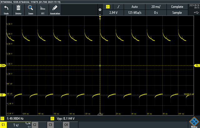
I am using the DRV8833C to drive a stepper motor, (rotation freq is 8Hz) the driver is in full step and everything seems to be ok (PWM stable and shifted for each 2input) figure 1 is the pwm before connecting the chopper. 

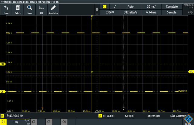
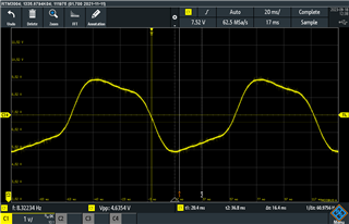
when i plug the stepper motor the pwm becomes like in fig2 (tuggeling) and this generate noise in the output signal that i measure un the DAQ channel (fig3). 

Do you know where this could come from ? 

fig1 . 

fig2

.

fig3.

waiting to hear from you.

Best regards.

  • Hello Hamza,

    It looks like the device is going into current regulation which explains the faster switching in the output voltage waveform. You can confirm if this is the case by measuring the AISEN and BISEN voltage. If the voltage >200mV, the driver is in active current regulation mode. 

    To disable the current regulation, tie AISEN and BISEN directly to GND or choose a sense resistor such that the voltage drop across it is less than 200mV when driving.

    Regards,

    Pablo Armet

  • Hello Pablo, 

    Thank you for your respond and sorry for my late reply, 

    I had the chance to do the necessary modifications and test the driver and it seems to be working as attached! 

    Last question: is it normal that the power supply starts switching (i noticed this in the Eval Board as well) when the chopper is plugged in ? 

    Waiting to hear from you.

    Best regards.

    Hamza

  • Hello Hamza,

    Pablo is currently out of office. He will respond to you when he is back tomorrow.

    Best,

    Keerthi 

  • Hello Hamza,

    Last question: is it normal that the power supply starts switching (i noticed this in the Eval Board as well) when the chopper is plugged in ? 

    Can you clarify what you mean? Are you referring to the power supply to the board switching or the driver outputs?

    Regards,

    Pablo

  • Hello Pablo:

    Yes, the power supply to the board exhibits instability when driving the stepper motor, with current fluctuating between 0.132A and 0.137A is that normal?.

    I have another question:

    In Figure 1, you can observe the driver output (without the stepper), where I obtained a clean PWM signal. In Figure 2, when the stepper is driven, you can see a noticeable slop. Is this slop attributed to the coil within the motor? If so, is it feasible to reduce its magnitude?

    Since I am in the process of redesigning the stepper driver, the current design employs a discrete component H-bridge. I have noticed that there is slop as well when I connect the driver, although it is considerably lower than when using the DRV8833

    figure1:

    figure 2: 

    Actual driver output when the stepper is driven (it's using PCM not PWM but i'm only focusing in the magnetiude and as you can see it's lower than what i got using the DRV8833)

  • Hello Hamza,

    In Figure 1, you can observe the driver output (without the stepper), where I obtained a clean PWM signal. In Figure 2, when the stepper is driven, you can see a noticeable slop. Is this slop attributed to the coil within the motor? If so, is it feasible to reduce its magnitude?

    Were the two figures taken with the same motor and same control configuration (xIN1 and xIN2 are the same for both Figure 1 and Figure 2)?

    Regards,

    Pablo Armet 

  • Hello Pablo! 

    Yes the two figures were obtained for the same configuration (same stepper motor and same PWM ) .

    Best regards

  • Hello Hamza,

    Yes, the power supply to the board exhibits instability when driving the stepper motor, with current fluctuating between 0.132A and 0.137A is that normal?.

    Some fluctuations in the power supply current is possible. Try increasing the capacitance on the power supply line. It can help reduce some of these ripples.

    In Figure 1, you can observe the driver output (without the stepper), where I obtained a clean PWM signal. In Figure 2, when the stepper is driven, you can see a noticeable slop. Is this slop attributed to the coil within the motor? If so, is it feasible to reduce its magnitude?

    Yes. The inductance within the motor winding can cause some slops in the output voltage and current waveforms. To test if this is the case in your design, try adding series inductance at the output and observe if the slop is reduced.

    Regards,

    Pablo Armet

  • Hello Pablo,

    Thank you for your replu, 

    I will try to integrate those changes in my design.

    Best regards.

    Hamza

  • Hamza,

    Let me know if the suggested changes help.

    BR,

    Pablo