This thread has been locked.
If you have a related question, please click the "Ask a related question" button in the top right corner. The newly created question will be automatically linked to this question.
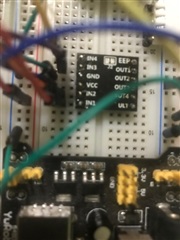
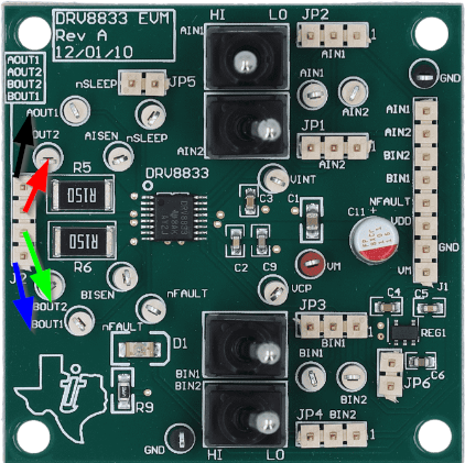
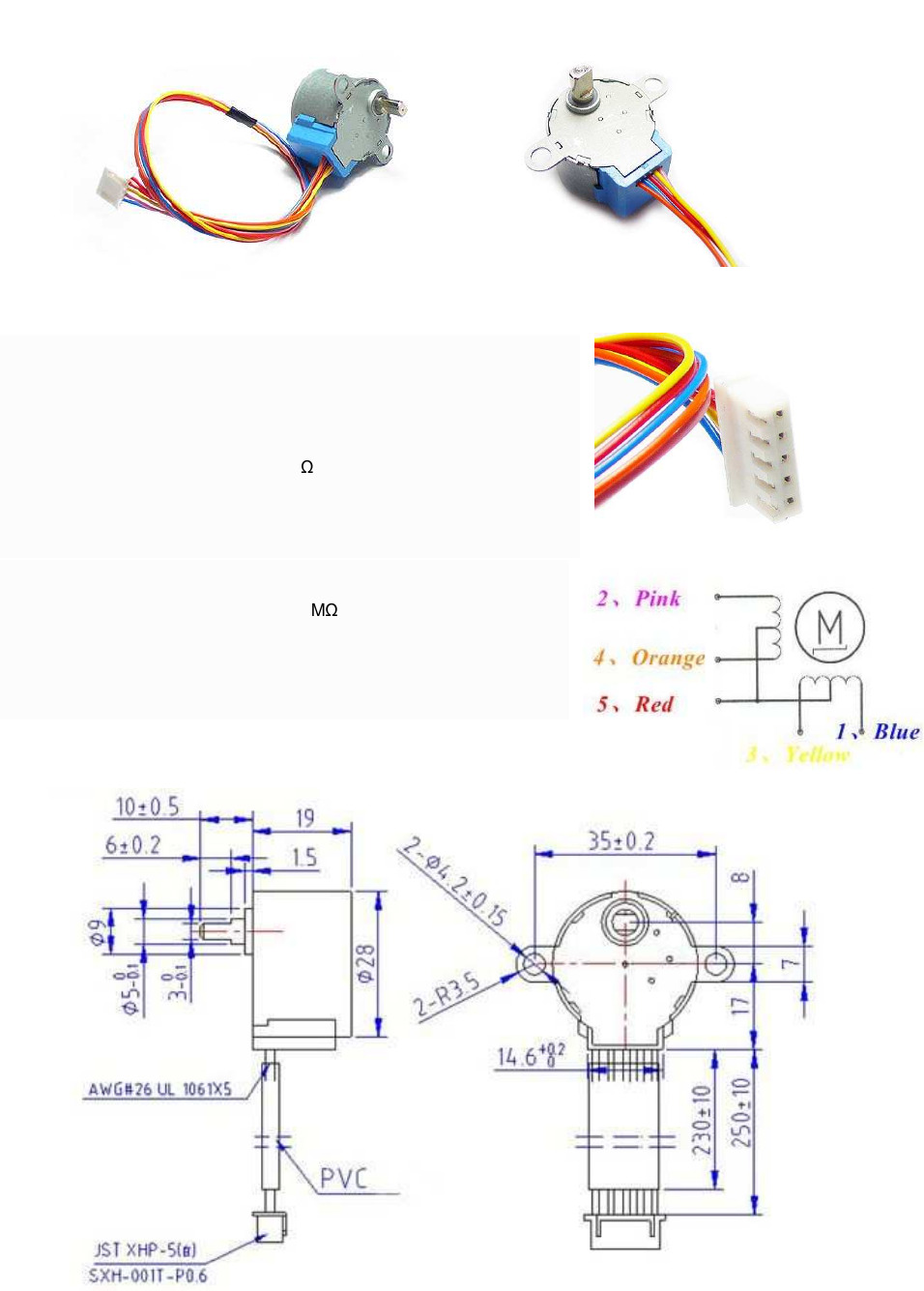
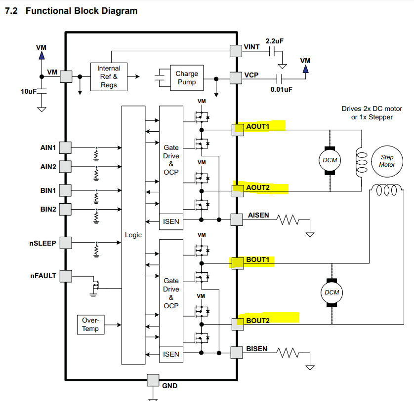
Trying to work on the project presented in Ti bulletin tiduah5 and I don't see any labels in the diagrams or photos for output pins of the DRV8833 except a problematic color coded wire with no legend. What does one do if they use another motor ? Also, I am not using the $50 eval board for the DRV8833, rather the $2 chips on a breakout board as shown below. Can someone comment on the motor to DRV8833 connections. I think there are 4 pins for outputs + 2 pins for other stuff. Also the Vexta 7 doesn't come with voltage on the badge so I'm not sure what I am supposed to supply. Thank you.
I'm running the code now and my stepper just twitches with random motions in random directions. Lots of vibration also. I found a data sheet for this motor and it says it is rated at 2.72 volts. Not sure where that goes ? Certainly the DRV8833 won't turn on unless it's getting 5v. Do I put a resistor somewhere ? Had I done this in my usual Kyle, I might have been able to debug it. Unfortunately, this is my first real go with Code Composer so I can't seem to figure out how to debug this.
I got this to work finally. i did not solder the jumper for enable and there is no connection or code to pull it high into the enable state. Unfortunately, my stepper just turns about 90 degrees and stops. I was hoping it would just keep running until i turned it off. I still don't understand how to feed this chip the correct voltage to match my stepper.
Hi Charles,
Can someone comment on the motor to DRV8833 connections.
The four output connections refer to the H-Bridge A (AOUT1: Black, AOUT2: Red) and H-Bridge B (BOUT1: Blue , BOUT2: Green ). The order is followed from the above legend on the EVM.
Lots of vibration also. I found a data sheet for this motor and it says it is rated at 2.72 volts. Not sure where that goes ?
The motor used in the application will need to be rated for the motor drivers voltage. Your VM (motor voltage) supplied to the DRV8833 is the same voltage that is across your motor.
I still don't understand how to feed this chip the correct voltage to match my stepper.
Your VM (motor voltage) supplied to the DRV8833 is the same voltage that is across your motor. The stepper motor is controlled through PWM input signals that are generated from the MCU.
Please refer to the DRV8833EVM users guide for any other issues:
Best,
David
Hi Charles,
Following up with you regarding your DRV8833EVM questions in the ARM microcontrollers forum. In that post you mentioned a 5-wire unipolar stepper motor and a NEMA17 stepper motor.
Below is the information you provided for the 5-wire stepper.
Unipolar motors are driven differently compared to a bipolar stepper motor. With the aforementioned unipolar you said you ignored the common red wire and left it as no connect NC. In this case the coil connections pink and orange wires would be phase A and the coil connections yellow and blue wires would be phase B. Because the center tap of both coils are shorted together in the 5-wire stepper motor, it can be used only in full-step mode while driven with a bipolar drive IC. You can write your own code with the sequence mentioned in this application note, https://www.ti.com/lit/an/sloa312/sloa312.pdf. There are also plenty of examples in the public forum. A simple sequence will get you running the motor.
Many low cost steppers do not follow a color convention for the coils. It is easier to identify the individual phases using a multimeter especially a 4-wire bipolar stepper motor. I have come across many bipolar steppers with RED/BLUE as one pair (A-phase) and BLACK/GREEN as another pair (B-phase). If A and B phases are interchanged it will still run fine except the direction will be changed. I have also seen coil pairs like David mentioned. Best would be to identify with a multimeter and find each individual coil wire pairs and connect them to AOUT1/AOUT2 and BOUT1/BOUT2. You can find a lot of public information on this subject on the internet. For example, https://3ddistributed.com/duet-wifi/stepper-motor-wire-color-and-coil-pairs/. The below diagram represents a bipolar stepper motor connection.
The above information should address driver connections to the stepper motor. You had another question "I found a data sheet for this motor and it says it is rated at 2.72 volts. Not sure where that goes?". In some motor specifications rated voltage is a specification. However in reality what matters in a stepper motor is the rated current required to output the rated torque. The rated voltage simply means the voltage required to drive the rated current to the motor while using a direct drive to the coil. For example this datasheet https://www.mouser.com/datasheet/2/758/stepd-01-data-sheet-1143075.pdf states the rated voltage is 5V and DC resistance is 50 Ω. So the rated current is 5/50 = 100 mA. This is the spec that will be needed for a modern chopper based current regulating stepper drivers. The below formula shows how the coil current can be set. For 100 mA a 2 Ω sense resistor must be used. If a supply voltage of 12 V is used still the current will be regulated at 100 mA and not 12 V / 50 Ω. Some stepper datasheets are good about providing a maximum voltage of operation or insulation voltage.
Take a look at this datasheet example, https://www.moonsindustries.com/p/nema-17-high-precision-hybrid-stepper-motors/ms17ha4p4040-000004611110015909. The rated current is 0.4 A. Check out the Torque Speed Curves. This shows curves for 12, 24, 36 and 48 V operation with the same current. This is while using a chopper based current regulated stepper drive.
That said for simplified operation you can consider a STEP/DIR interface stepper driver that has built-in indexer so you won't have to code the indexer in a microcontroller. For example, https://www.ti.com/lit/ds/symlink/drv8434.pdf.
Regards, Murugavel
Thank you for your thorough answer/ You must have spent a lot of time on it as apparently David did also. By the way, I'm using the cheap little expansion board versions of the chip and not the Evaluation Board. Cheers and thanks again.